












Use this guide after the project has defined its life-safety task and chosen the overall emergency-lighting architecture. It focuses on the component-level decision: matching the emergency driver, battery, LED load, control path, operating environment and test evidence as one approved configuration. If the project is still comparing self-contained luminaires, central batteries, inverters or generator-supported systems, start with How to Choose an Emergency Lighting System.
Once the architecture is fixed, do not compare drivers by wattage or batteries by nominal capacity alone. The release decision must connect the selected LED load, emergency output, conversion losses, battery discharge conditions, charging behavior, temperature, controls and test endpoint to one assembled configuration.
Record the Approved Project Basis Before Component Selection
Component selection begins only after the responsible project team has approved the jurisdiction, life-safety task, emergency-lighting architecture and acceptance route. Record those items as fixed inputs. A supplier can provide component and test evidence, but it cannot replace the building design or the authority’s interpretation.
For workplaces in the United States, OSHA requires exit routes to be adequately lighted and exit signs to use a reliable illumination source. Those provisions establish outcomes for the route and sign; the approved project design must still define the emergency output, duration, operating states and architecture that the component package must support.
| Approved project input | Record before component selection | Component decision it controls |
|---|---|---|
| System architecture | Self-contained, central-battery, inverter or other approved arrangement | Defines where conversion, storage, charging and monitoring occur |
| Emergency lighting task | Required output, distribution and served LED load | Defines the electrical load and emergency operating point |
| Duration and endpoint | Required operating period and end-of-test acceptance criterion | Defines battery duty and the evidence needed for release |
| Environment and service plan | Temperature, enclosure, access, testing and replacement route | Defines component limits, installation and maintenance evidence |
Define the Driver–Battery–LED Load Compatibility Boundary
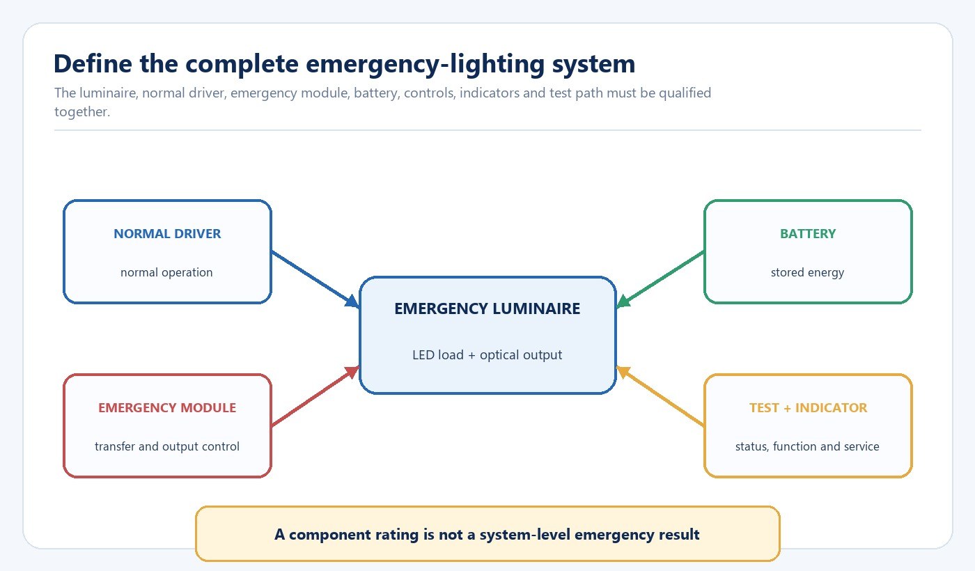
List the normal luminaire, normal driver, emergency control gear or inverter, battery, charge indicator, test device, local controls, protective devices and any central monitoring interface. Identify which part senses supply failure, which path powers the LED load during emergency operation and which device controls charging.
Record who supplies, integrates, tests and maintains every element. A complete luminaire may arrive as one controlled assembly; a converted fitting may combine components from different parties. The evidence request should match that responsibility boundary.
Translate the Selected Architecture Into Operating States
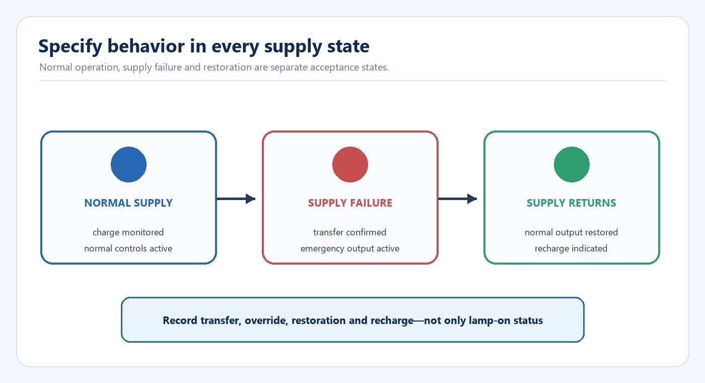
Maintained and non-maintained describe operating behavior, not the location of the battery. A maintained emergency luminaire also operates while normal supply is present; a non-maintained unit is intended to operate when the normal supply fails. A combined arrangement may include both functions. Show the state in a circuit or cause-and-effect diagram instead of relying on the label alone.
For each state, define the active power path, output level, local-switch behavior, dimming response, indicator state and monitoring signal. Also define restoration: whether normal output returns immediately, whether controls resume their previous state and how recharge or a fault is indicated.
Translate Emergency Output and Duration Into Battery Duty
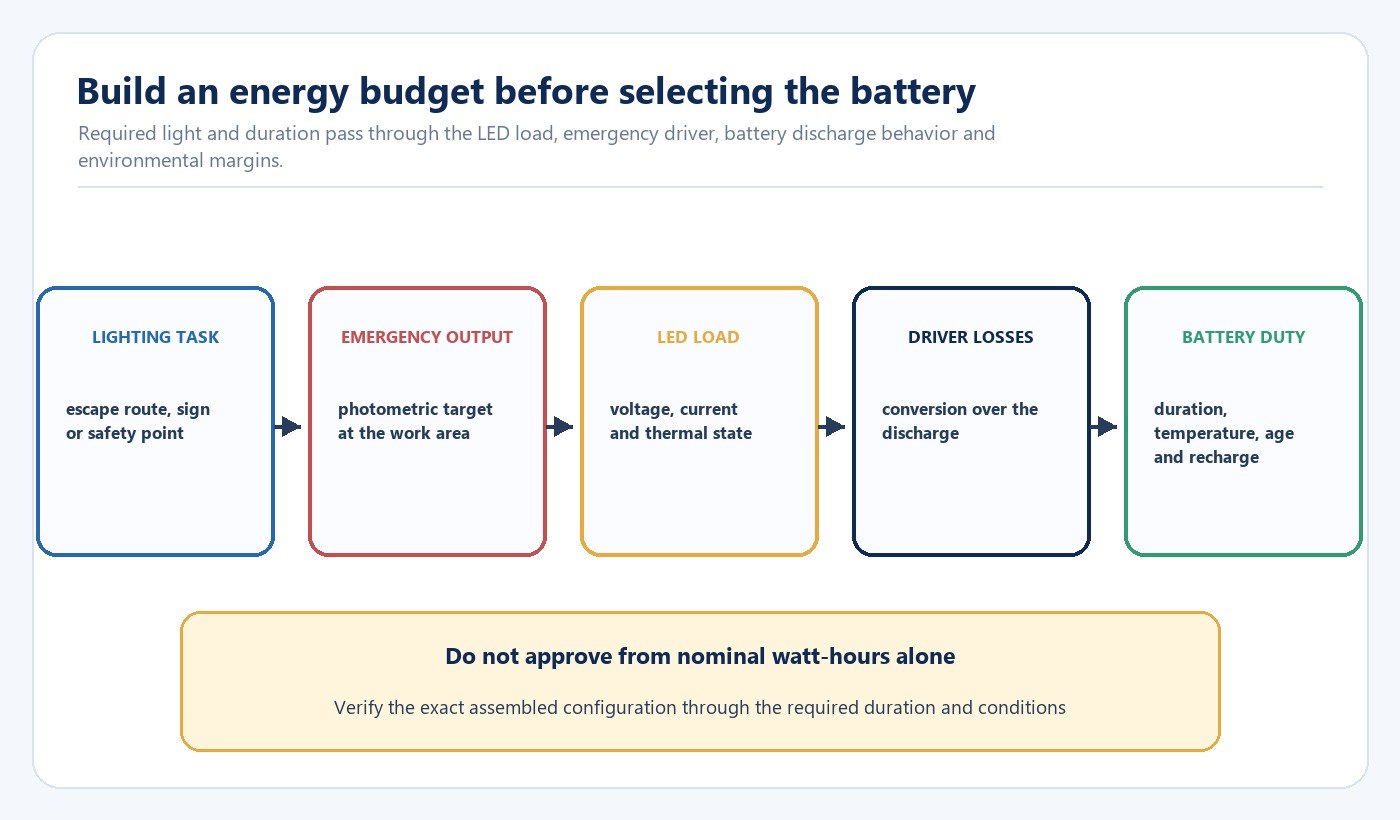
Do not calculate battery selection as emergency watts multiplied by hours and stop there. That product gives an ideal energy figure, not a verified system result. The available energy changes with battery chemistry, discharge rate, temperature, aging, cut-off voltage and recharge history. The emergency converter also has losses that can vary through the discharge, and the LED load may not behave like a fixed resistor.
Use the calculation to build the first engineering estimate, then verify the assembled configuration. Record the required emergency output at the luminaire or task area, the LED load range accepted by the emergency driver, the required duration, the environmental range and the end-of-duration acceptance criterion. Ask for a discharge curve or duration test that matches the intended battery and load.
| Evidence item | What it should identify | Decision it supports |
|---|---|---|
| Emergency-driver load range | LED voltage, current, power and connection method | Whether the exact LED load is supported |
| Battery data | Chemistry, nominal rating, cut-off, temperature and charge conditions | Whether the stated duty is comparable to the project |
| Duration test | Exact luminaire, driver, battery, ambient and output measurement | Whether the assembled configuration reaches the required endpoint |
| Recharge evidence | Charge state, indication, time basis and fault behavior | Whether readiness can be restored and monitored |
Coordinate Normal Controls With Emergency Override
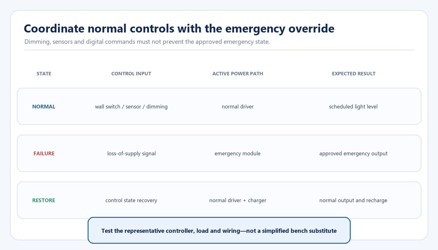
Document what happens when normal power is present, when it fails and when it returns. Confirm whether the normal driver is bypassed, how dimming commands are handled, whether a local switch is overridden and how occupancy sensors or digital controls behave. A representative circuit test should include the intended controller, load, wiring arrangement and programmed settings.
An emergency module may power the same LED load through a different electrical path, so normal dimming compatibility does not prove emergency compatibility. Likewise, a lamp that illuminates during a bench power cut has not demonstrated the required control override, output, duration or restoration behavior. Use the driver, dimming and control compatibility guide to define the wider control test, then add the emergency state transitions shown here.
Check Temperature, Charging and Service Conditions
Battery life and available duration depend on the environment and duty. Record the temperature at the battery location, nearby driver heat, enclosure ventilation, mounting orientation and expected normal operating hours. A battery located beside a hot driver or inside a tight enclosure may experience a different condition from the ambient room temperature.
Confirm charging input, charge indicator, protection behavior and the response to a disconnected or failed battery. The design should provide access for inspection and replacement without disturbing unrelated safety-critical wiring. Labels should identify the approved battery type, connection and replacement instructions for the maintained record.
The LED product compliance document checklist helps connect model identity, controlled construction, labels and instructions to the exact released configuration.
Plan Functional, Duration and Restoration Tests
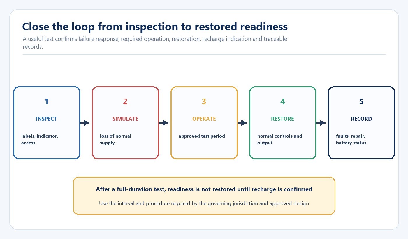
The test plan should distinguish a short functional check from a full-duration test. A functional check confirms that the emergency state starts and the relevant lamps operate. A duration test confirms operation through the required period and endpoint under the approved procedure. Restoration checks then confirm normal controls, indication and recharge behavior.
The UK Home Office office-and-shop guide gives an example regime that includes routine visual checks, monthly function tests and an annual full-discharge test, while noting that other regimes may be appropriate. It also warns that batteries typically need time to recharge after a full discharge. Use the interval and procedure required by the governing jurisdiction, system design and manufacturer’s instructions; do not copy the example schedule into another market without checking applicability.
Record the product identity, battery identity, date, starting condition, test method, duration, result, faults, corrective action and person responsible. The LED lighting sample evaluation checklist can be used to reconcile the tested sample with the approved model and deviations.
Freeze the Approved Configuration Through Production
The approved result belongs to a defined luminaire, LED load, emergency driver, battery, wiring arrangement, indicator, firmware or settings and test method. A replacement that fits physically may change current, conversion efficiency, thermal exposure, charge behavior or end-of-duration output.
Use controlled part numbers and revisions for critical components. Route changes through an impact review that identifies affected drawings, samples, tests, labels and instructions. New Lights’ factory and manufacturing capabilities page provides the relevant route for discussing sampling, production coordination and controlled manufacturing evidence without treating a general factory process as proof of emergency performance.
Build the RFQ and Release Checklist
- Identify the jurisdiction, occupancy, emergency-lighting design basis and approval responsibility.
- Define the safety objective, luminaire positions and emergency output requirement.
- State maintained, non-maintained or combined behavior for every supply state.
- Draw the normal, failure, restoration and recharge paths, including controls and monitoring.
- Identify the exact luminaire, LED load, emergency driver, battery and wiring configuration.
- Record duration, environmental range and end-of-duration acceptance criteria.
- Require configuration-specific functional, duration and restoration evidence.
- Approve indicator visibility, test access, battery access and replacement records.
- Freeze critical parts and define which changes require requalification.
- Assign testing, maintenance and record-retention owners.
Review applicable New Lights lighting solutions for the project context. To discuss an exact installation, contact New Lights with the jurisdiction, emergency-lighting design, circuit diagram, luminaire load, required duration and control sequence.
Frequently Asked Questions
Can an emergency driver be selected by luminaire wattage alone?
No. Compatibility also depends on LED voltage and current, emergency output, duration, battery duty, conversion losses, temperature, controls, wiring and the tested assembled configuration.
Is nominal battery watt-hour capacity enough to prove duration?
No. It is an input to an estimate. The release decision needs configuration-specific evidence that includes the battery, load, converter, environmental conditions, discharge endpoint and required operating period.
What is the difference between maintained and non-maintained operation?
A maintained emergency luminaire also operates during normal supply. A non-maintained unit is intended to operate when normal supply fails. The project diagram should show the exact control and transfer behavior.
Who sets the emergency duration and test frequency?
The governing jurisdiction, adopted standards, approved building design and maintenance responsibilities determine them. Supplier instructions support the procedure but do not replace the project basis.
Editorial Sources
- UK Home Office, “Fire safety risk assessment: offices and shops”: https://www.gov.uk/government/publications/fire-safety-risk-assessment-offices-and-shops/fire-safety-risk-assessment-offices-and-shops-accessible
- U.S. Occupational Safety and Health Administration, “Maintenance, Safeguards, and Operational Features for Exit Routes”: https://www.osha.gov/etools/evacuation-plans-procedures/emergency-standards/maintenance-safeguards-features