











An artificial skylight can be level and securely mounted while its visible light patch is still shifted, distorted or inconsistent. Structural stability keeps the opening, frame and optical assembly in their intended relationship, but the final effect also depends on optical orientation, room surfaces, viewing position and control state. Align the project with shared datums, then verify the patch after warm-up from every agreed viewing zone.
This is an architectural-lighting task. New Lights P and X Series products create ceiling- or window-style daylight effects for interiors; they should be specified and commissioned as artificial skylights, not as photovoltaic laboratory solar simulators.
Confirme se o Projeto Utiliza a Série P ou X
The current P Series Modular Ceiling Artificial Skylight page identifies a recessed ceiling format. Its published model XGYSSL-YRP3060-E45 measures 582 × 282 × 36 mm with a 527 × 227 mm active area and is coordinated with an X1 keel interface. Multiple modules can form a larger ceiling composition.
The X Series Window-Style Artificial Skylight page identifies a wall-mounted format. The published XGYSSL-YRX13078-E160 body measures 1332 × 781 × 60 mm and contains four 527 × 227 mm light sections behind the optical surface. It requires a wall opening, structural support, wiring path, driver space and service access.
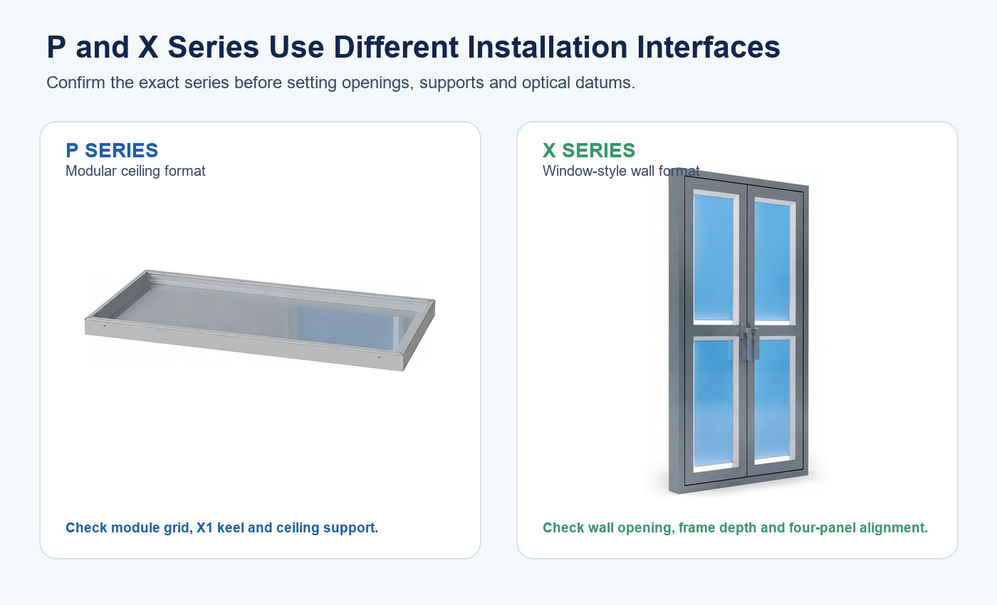
| Decisão | Formato de teto da Série P | Formato de janela da Série X |
|---|---|---|
| Interface principal | Suporte de teto embutido e grelha de módulos | Abertura de parede e corpo com caixilho |
| Área ativa publicada | 527 × 227 mm per listed module | Four 527 × 227 mm light sections |
| Foco de coordenação | Perfil estrutural, espaçamento dos módulos, nível do teto e acesso acima | Abertura, profundidade do caixilho, planura da parede e alinhamento dos painéis |
| Revisão visual | Repetição entre módulos de teto | Continuidade na composição de janela de quatro painéis |
| Desenho necessário | Planta de teto refletido e corte | Alçado de parede, planta e corte |
Utilize a página mais abrangente de página de soluções de claraboias artificiais e luz natural para comparar formatos de produtos. Não transfira a descrição da abertura, do suporte ou da ótica de uma série para a outra.
Defina a Mancha de Luz Antes de Projetar a Abertura
“Accurate light patch” needs measurable project language. Mark where the effect should appear, how large it should be, which direction it should extend and from where it will be viewed. A patch centered in a photograph may appear displaced to a person standing elsewhere.
Define the primary and secondary viewing zones, standing or seated eye height, important room surfaces and control scenes. Record the intended patch center, boundary, orientation, edge softness, brightness relationship and acceptable visible seams. If the product is meant mainly to create a luminous sky surface rather than a projected patch, define panel uniformity and apparent depth instead.
| Requisito | Registar antes da instalação | Evidência de aceitação |
|---|---|---|
| Localização da mancha | Centro e limite a partir das referências da divisão | Coordenadas medidas após estabilização |
| Dimensão e forma da área iluminada | Dimensões-alvo e descrição da extremidade | Fotografia assinalada mais medições físicas |
| Zonas de observação | Localizações em planta e alturas dos olhos | Rever a partir de todas as posições indicadas |
| Condição da superfície | Pressupostos de cor, textura e refletância | Acabamento final ou maquete representativa |
| Estado de controlo | CCT, brightness and scene | Definição registada do controlador e estado elétrico |
| Aspeto do painel | Juntas permitidas, variação de luminosidade e visibilidade do caixilho | Revisão visual em estado estabilizado |
O guia de planeamento de projetos de claraboias artificiais abrange decisões iniciais de aplicação, assistência e aquisição. Este artigo aborda a tarefa mais específica de alinhamento e aceitação.
Coordene a Abertura, o Suporte e a Superfície Acabada
Use one coordinated drawing set for architecture, structure, reflected ceiling or wall elevation, electrical routing and service access. Show the rough opening, finished opening, product body, support frame, trim, active surface and removable components separately.
The decorative ceiling grid or wall finish should not be assumed to carry the product. Define the load path and fixing points using the product and project requirements. Check clashes with ducts, pipes, sprinklers, speakers, sensors, studs and access panels before fabrication.
Record opening width, height, diagonals, depth, level, plumb and twist. A rectangular opening can have correct width and height while being out of square. A long edge can be level at its ends but bowed at the center. These deviations can create uneven perimeter gaps or shift the optical assembly relative to the room.
Estabeleça Referências Estruturais e Óticas Comuns
Choose a centerline, finished-surface datum, mounting depth and optical direction that all trades can use. Transfer those references to the opening, support frame and product. Do not align solely to an uneven tile edge or decorative joint.
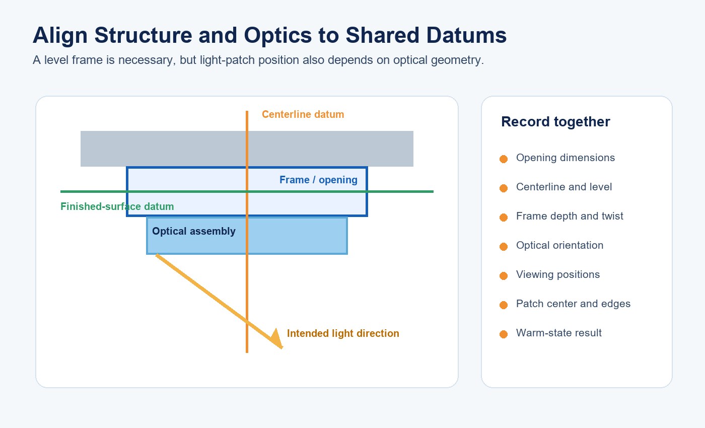
Mark the optical axis or reference plane on the shop drawing. For a ceiling module, relate it to the module grid and room centerline. For a window-style unit, relate it to the wall elevation, finished floor and viewing direction. If the optical assembly has an intentional tilt or reflective path, distinguish that angle from frame level.
Measure and photograph the hidden support before finishes close it. Keep the actual coordinates with the drawing revision; photographs alone rarely prove level, depth or twist.
Compreenda Porque a Estabilidade Estrutural Altera o Resultado Visual
Frame movement can change optical spacing, panel flatness, seam alignment and perimeter gaps. Deflection at a support point may rotate the product even when the visible trim looks acceptable. Differential movement between adjacent modules can make a continuous sky composition appear stepped.
Optical sensitivity depends on the product geometry. The New Lights catalogue describes the P Series as an ultra-thin ceiling format and the X Series as a window format using a reflective path. A change in distance or angle between source, reflector and optical surface can shift brightness or the apparent patch.
Structural stability therefore supports repeatability, but it is not the only variable. Source output, diffuser or reflector position, surface finish, controller setting and viewing angle also affect the result. Diagnose these variables before moving a correctly installed frame.
Defina a Flecha e o Movimento ao Nível do Projeto
There is no useful universal deflection number for every artificial skylight. Set allowable movement from the product drawing, structural design, module size, joint detail and visual tolerance. A small change may be visible at a narrow seam or long illuminated edge even when it is structurally acceptable.
Review self-weight, cables, remote drivers, trims, service loads and surrounding construction. Consider vibration, door movement, maintenance access and building movement. For multi-module arrangements, check relative deflection between units as well as absolute level.
| Fonte de movimento | Possível sintoma visual | Evidência a verificar primeiro |
|---|---|---|
| Abertura fora de esquadria | Folga perimetral irregular ou caixilho torcido | Diagonais e níveis dos cantos |
| Flecha do suporte | Superfície inclinada ou mancha deslocada | Espaçamento dos suportes e medições do caixilho sob carga |
| Variação entre módulos | Desnível, junta ou descontinuidade de luminosidade visível | Profundidade individual do módulo e orientação ótica |
| Movimento térmico | Folga ou alteração de alinhamento em estado estabilizado | Medições a frio e após estabilização |
| Movimento do acabamento | Sombra do remate ou desalinhamento aparente | Plano do acabamento versus referência estrutural |
Considere a Geometria em Estado Estabilizado
LEDs, drivers and the optical assembly warm during operation. Different materials can expand by different amounts, changing gaps, contact pressure or panel flatness. Test geometry and appearance after the product reaches a stable operating condition, not only immediately after switch-on.
Record room temperature, input voltage, power, control state and elapsed time. Compare cold and warm measurements at the same points. If a change appears, separate normal material movement from loose fixing, inadequate support, optical-part displacement or an electrical-control issue.
Ventilation and clearance changes can affect temperature, light leakage and serviceability. Follow the approved installation documents rather than cutting openings or blocking cavities as an informal correction.
Construa uma Maquete Representativa à Escala Real
A small panel sample cannot prove room-scale patch position. Use the actual product, support detail, opening, finish, wall or ceiling color, viewing distance and control system. Include the most sensitive corner, seam or long edge in a multi-module layout.
Review the mockup before enclosure so that support, datums, wiring and service routes are visible. Then complete the finish and repeat the optical review. The existing guia de instalação de claraboias artificiais tipo janela fornece detalhes adicionais sobre abertura de parede e acesso para assistência em projetos da Série X.
Durante a maquete, registe:
- Modelo do produto, revisão e disposição dos módulos.
- Medições da abertura, do suporte e da superfície acabada.
- Controller, CCT, brightness and scene.
- Centro da mancha, dimensões, aspeto das extremidades e uniformidade dos painéis.
- Observações das zonas de observação, encandeamento e juntas visíveis.
- Resultados de arranque a frio e após estabilização.
Utilize posição fixa da câmara, exposição e balanço de brancos para fotografias comparativas. Mantenha as medições como registo de aceitação principal.
Comissione com um Fluxo de Trabalho Baseado na Causa
Commissioning should reproduce the approved mockup rather than create new acceptance rules on site. Confirm model identity, drawing revision, support, fasteners, opening, level, plumb, twist, perimeter gaps, wiring, controls and service access before judging the patch.
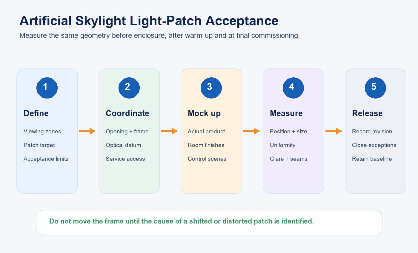
If the patch is wrong, compare frame position, optical orientation, controller state, internal optical parts, room finishes and measurement reference. Changing the frame may hide the symptom while creating an opening, trim or service problem.
O guia de resolução de problemas e manutenção de claraboias artificiais fornece uma via separada para sintomas em fases posteriores de vida útil. Mantenha as medições originais de comissionamento como referência de manutenção.
Controle Dimensões Personalizadas e Revisões de Produção
Custom dimensions can change weight, stiffness, support spacing, optical path, driver arrangement and thermal behavior. Treat each approved custom configuration as a controlled revision. Freeze dimensions, materials, color, seams, mounting details, controller behavior and acceptance method before production.
Link the approved sample, drawings, bill of materials and mockup record. Identify which changes require a drawing update, repeated optical review or new sample. New Lights’ capacidades de fábrica e de fabrico fornecem a via para controlo de amostras e coordenação da produção.
For multi-panel projects, define module labeling and replacement strategy. A future replacement should reproduce optical orientation, control behavior and visible appearance without rebuilding the entire composition.
Prepare o RFQ da Claraboia Artificial
Provide room plans, reflected ceiling or wall elevations, sections, finished opening, support constraints, viewing zones, intended visual effect, control scenes, service route, quantity and delivery sequence. State whether the project uses a ceiling P Series format, window X Series format or another artificial-skylight family.
Request the exact model drawing, weight and fixing information, active-area dimensions, optical orientation, electrical and controller requirements, photometric evidence, access method and project-specific acceptance plan. For a defined review, contacte a New Lights com a abertura, o acabamento, o suporte e a posição prevista da mancha.
| Item do pacote RFQ | Resposta necessária do fornecedor | Condição de aprovação |
|---|---|---|
| Identidade do produto | Modelo, revisão e série exatos | Corresponde ao desenho, à amostra e à cotação |
| Interface de instalação | Dimensões do corpo, abertura, suporte e fixação | Coordenado com os desenhos arquitetónicos e estruturais |
| Intenção ótica | Área ativa, orientação e evidência fotométrica disponível | Corresponde à área iluminada definida ou ao requisito de superfície luminosa |
| Controlos | Interface, scenes, CCT and brightness behavior | Demonstrado na maquete aprovada |
| Configuração personalizada | Dimensões, materiais e evidência afetada alterados | Desenho revisto e revalidação delimitada aceites |
| Entrega | Dados conforme construído, definições, medições e método de assistência | Referência completa retida pela equipa do projeto |
Perguntas Frequentes
Uma claraboia artificial arquitetónica é um simulador solar PV?
No. These P and X Series products are architectural interior-lighting formats. Photovoltaic test equipment has a different intended use and measurement framework.
Um caixilho nivelado garante uma mancha de luz centrada?
No. Level is one input. Optical orientation, source and reflector position, room surfaces, controls and viewing position also influence the visible result.
O alinhamento deve ser verificado antes ou depois do aquecimento?
Check both. Cold measurements confirm installation geometry; stabilized measurements reveal changes associated with operating temperature and output state.
Can a custom size use the standard model’s acceptance record?
Not automatically. Changed dimensions can affect support, stiffness, optical spacing and service access, so the revised configuration needs scoped evidence.
O que deve ser retido após o comissionamento?
Keep product identity, approved drawings, measured datums, control settings, warm-state patch measurements, photographs, exceptions and the final accepted revision.
Fontes editoriais
- New Lights, “P Series Modular Ceiling Artificial Skylight”: https://www.new-lights.com/products/artificial-skylights/p-series-modular-ceiling-artificial-skylight/
- New Lights, “X Series Window-Style Artificial Skylight”: https://www.new-lights.com/products/artificial-skylights/x-series-window-style-artificial-skylight/
- New Lights, “Sun Simulator Light” catalogue: https://www.new-lights.com/new-lights/2024/12/06/sunsimulatorlight.pdf
- International Electrotechnical Commission, “IEC 60904-9:2020 Photovoltaic devices — Classification of solar simulator characteristics”: https://webstore.iec.ch/en/publication/28973