A prismatic lens is a structured optical cover that redirects light from an LED array. In a linear luminaire, it can help blend the images of individual LEDs, shape the intensity distribution and control how the luminous aperture appears from different directions. The result depends on the complete optical system: LED pitch, source-to-lens distance, prism geometry and orientation, reflector shape, material, surface finish and any added diffuser.
The practical answer is therefore not simply “a prismatic lens improves uniformity.” First define which uniformity the project needs, then compare the exact luminaire with the lens installed. The New Lights LED linear fixtures category provides the product context; this guide explains the optical questions behind the cover.
Start with three different uniformity questions
Lighting discussions often use “uniformity” for different outcomes. Those outcomes are related, but they are not interchangeable.
| Uniformity question | What it describes | Useful evidence |
|---|---|---|
| Luminous-face uniformity | How even the illuminated lens looks when viewed directly | Calibrated luminance image or a defined luminance measurement grid |
| Intensity-distribution smoothness | How light is distributed by angle around the luminaire | Complete-luminaire photometric report, polar curves and IES file |
| Workplane illuminance uniformity | How evenly light reaches a desk, floor, shelf or other target plane | A calculation or mock-up using the exact photometry, room and layout |
Glare is a fourth evaluation rather than another synonym for uniformity. It depends on luminance, apparent source area, viewing direction, background and layout. A visually smooth lens can still present high luminance at an uncomfortable angle, while a visibly structured optic may produce a useful room distribution.
What a prismatic surface does to light
A prism changes a ray’s direction at an interface between materials. Depending on the incident angle, refractive index and surface geometry, a ray may refract through the optic, reflect at a surface, undergo total internal reflection or interact with another optical layer before leaving the luminaire.
DOE describes lenses, reflectors and diffusers as secondary optical elements used to extract light and tailor luminaire distribution. Their shapes, materials and attachment methods vary because the application and luminaire form factor change the design task. In a linear product, a prismatic pattern may run along the fixture, across it or in two directions. That orientation affects which plane receives stronger redirection.
A peer-reviewed LED solar-simulator study offers a useful mechanism example: its prismatic diffuser combined total internal reflection and refractive transmission, and the diffuser position changed the behavior of that particular optical stack. The transferable lesson is that geometry and spacing interact. Its numerical results belong to that apparatus and should not be reused as linear-luminaire performance values.
How source images become a luminous line
An LED board contains discrete packages rather than one continuous emitter. Each package sends light toward the cover. If neighboring ray fields do not overlap sufficiently before reaching the visible surface, the observer may see dots, stripes, bright bands or dark gaps.
The optical stack mixes those source images. A prismatic surface redirects some rays laterally or into neighboring viewing angles. Reflective sidewalls can return rays toward the aperture. A diffusing layer can reduce contrast between positions above an LED and positions between LEDs. The final appearance emerges from all of those interactions.
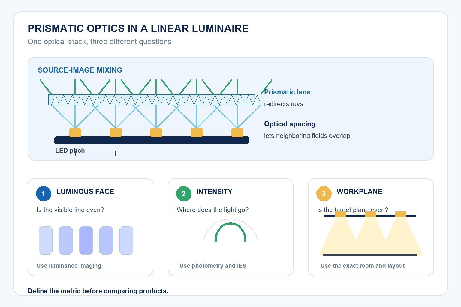
The main variables are:
- LED package emission pattern and package size;
- center-to-center LED pitch;
- distance from the LED board to the visible lens;
- prism pitch, angle, height and orientation;
- lens thickness, refractive index and surface finish;
- reflector position and reflectance;
- secondary diffusing layers or films;
- luminaire width, depth and edge treatment;
- assembly position and production tolerances.
Changing one variable can move more than one result. Additional diffusion may soften visible points but also alter transmission and angular distribution. Increasing source-to-lens distance can improve mixing in one design while increasing product depth. Reducing LED pitch may make blending easier, but it also changes package count, electrical loading and thermal density.
LED pitch and optical spacing must be evaluated together
LED pitch determines the distance between discrete sources. Optical spacing gives light from adjacent packages room to overlap before it reaches the aperture. Neither dimension sets a universal threshold because source emission and lens geometry differ.
During product development, compare pitch and spacing as a pair. A large pitch with a shallow cavity usually asks more of the optical surface. A smaller pitch can create a smoother source field, but the board and driver still need electrical and thermal review. A prism can redirect rays sideways, yet it cannot recover an unsuitable combination of source spacing, depth and target distribution by itself.
For procurement, record the production LED package, pitch, board layout and lens distance. A sample built with a different board is not a valid appearance reference for the final configuration. This is the same system-level principle used when comparing LED retrofit options: the visible light source, optical system and operating components must be evaluated together.
Prism orientation shapes the crosswise and lengthwise beam
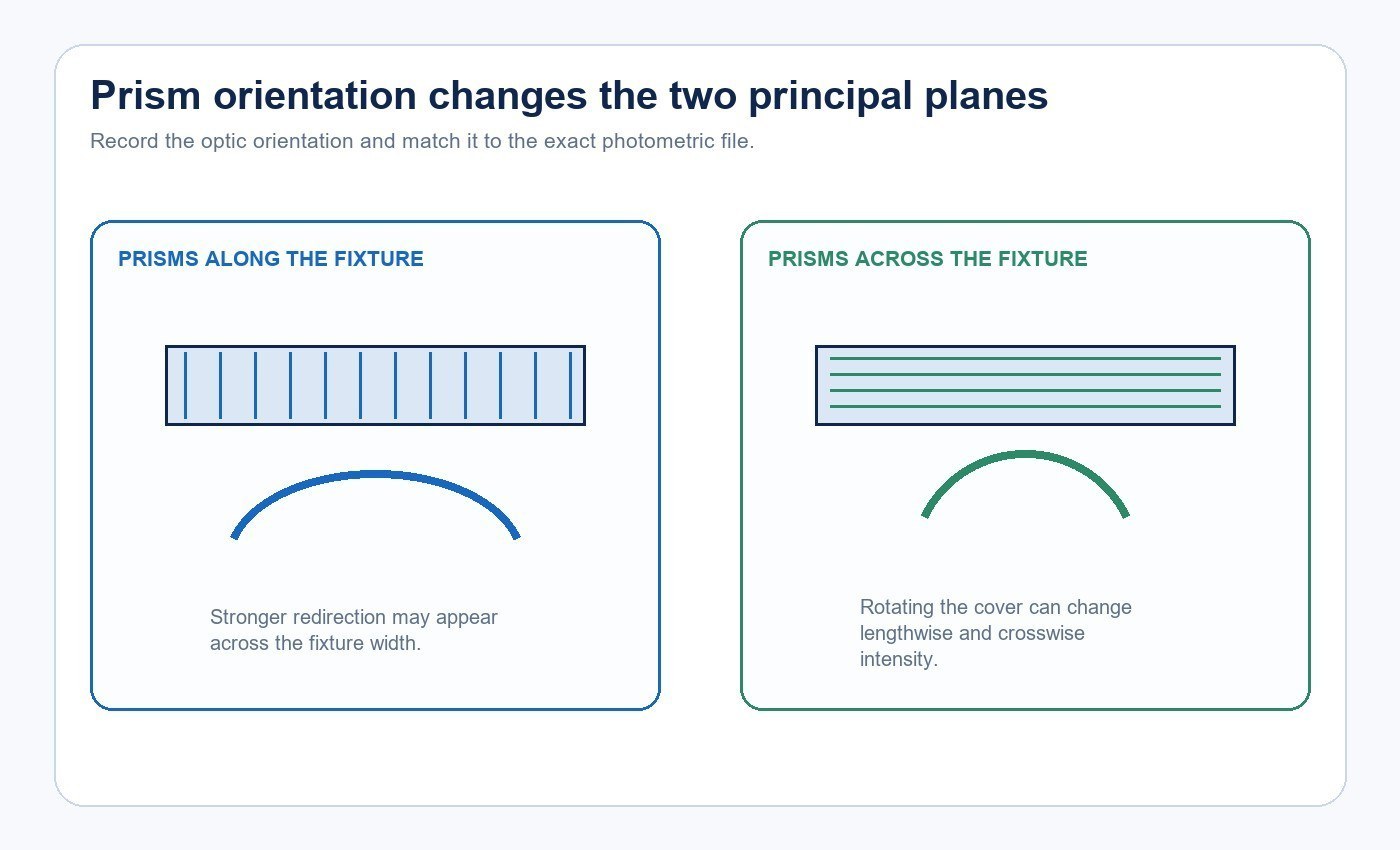
Linear luminaires often need different distribution along their length and across their width. A one-dimensional prism pattern can redirect light more strongly in one plane. Rotating that lens may change beam width, high-angle intensity and visible source texture.
The product drawing should identify orientation when it matters. Installation teams also need a clear way to preserve that orientation after the cover is removed for wiring or service. For asymmetric designs, request photometric data in the principal planes and confirm which end or face corresponds to the file orientation.
Prismatic, opal and clear optics are different tools
Product labels can be inconsistent, so examine the actual optical construction.
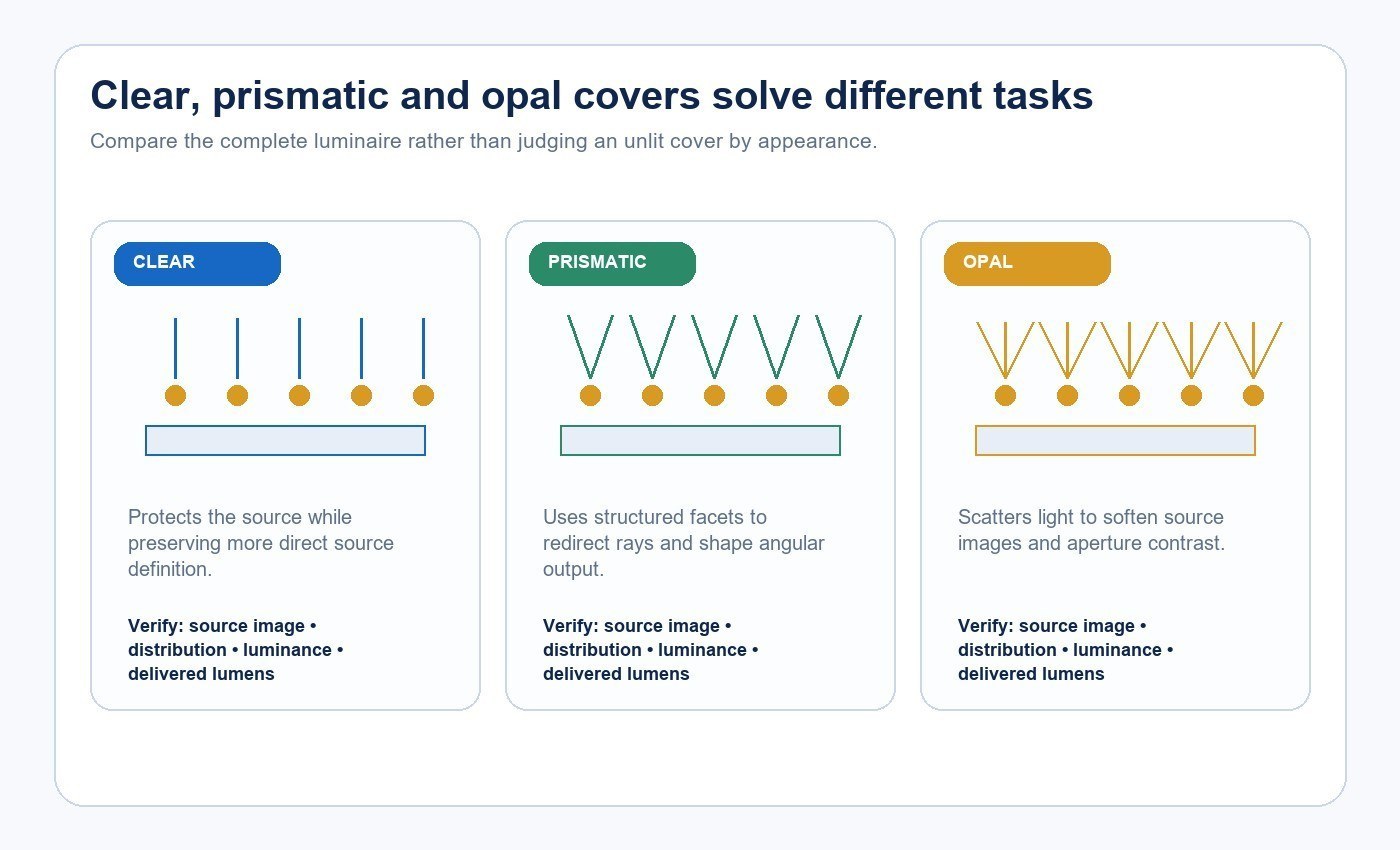
| Optical approach | Main role | Questions to ask |
|---|---|---|
| Clear cover | Mechanical protection with limited source-image hiding | Are individual LEDs visible, and is a separate lens used on the board? |
| Prismatic surface | Structured redirection through repeated geometric features | What is the pattern, orientation and target distribution? |
| Opal or translucent diffuser | Scattering that softens source images | What are the transmission, luminance and color effects? |
| Hybrid stack | Combines structured redirection with scattering or reflection | Which layers are present, and which measured configuration matches the offer? |
One label is not inherently superior. A clear-looking prismatic optic may produce strong source images at some angles. A highly diffusing cover may look smooth but send less light into the intended zone. Compare complete-luminaire output and distribution rather than judging only the unlit cover.
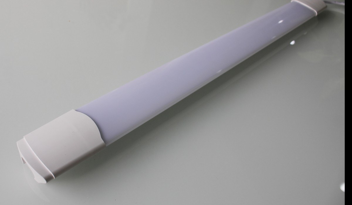
A smooth luminous face does not define the room result
Workplane illuminance depends on the complete luminaire distribution, mounting height, spacing, room surfaces and neighboring luminaires. Two products can look similarly smooth when viewed from below yet create different spacing patterns on the floor or desk.
DOE CALiPER testing of linear LED sources in troffers showed that source and luminaire distribution differences can change workplane illuminance uniformity. That system distinction matters for linear fixtures as well. Use the exact IES file in a calculation for the actual room. Review average, minimum and maximum values under the project’s chosen criteria, and include vertical surfaces when shelves, displays or faces matter.
An IES file is a standardized digital representation of angular luminous-intensity data. It supports calculation, but the file must match the offered model, length, power, optic and operating configuration. A generic family file can hide important differences.
Glare depends on luminance and viewing geometry
Prismatic optics may reduce direct views of individual LEDs or spread brightness over a larger apparent area. That can change visual comfort, but glare still depends on where the viewer is and what the room looks like.
IES discussion of non-uniform LED apertures highlights a central difficulty: lenses and diffusers change the apparent luminous area and luminance distribution. Review the luminaire from seated and standing positions, along and across its length, and near screens or glossy surfaces. Check high-angle intensity and aperture luminance rather than relying only on total lumens.
If a UGR value is supplied, ask for the photometric file and calculation conditions behind it. The flicker, power factor and THD buyer checklist covers a separate driver-related part of visual quality that the lens cannot solve.
Optical efficiency and material stability are part of the decision
Every optical interaction can transmit, reflect, absorb or scatter light. A design that improves source-image blending may redirect output away from the target zone or introduce additional loss. Compare complete-luminaire lumens, input power and angular distribution for each offered optic.
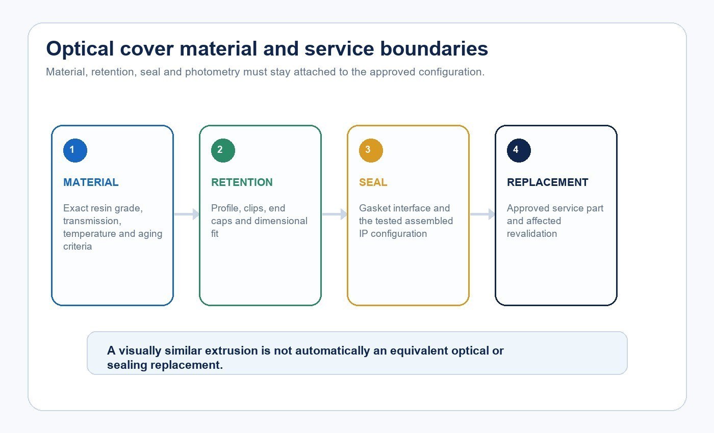
Material choice also affects production and service. DOE identifies common optical materials such as PMMA, polycarbonate, cyclo-olefin copolymers and silicone, each with different optical, thermal, environmental, molding and cost characteristics. The material name alone is not an acceptance criterion. Request the exact grade when it matters, then define the relevant appearance, dimensional and aging requirements for the application.
The cover may also be part of the retention and sealing system. Clips, end caps, gasket contact and extrusion tolerances can affect whether the assembled luminaire matches its tested ingress-protection configuration. Record those interfaces with the optic code rather than treating the cover as a cosmetic part.
A damaged cover should be replaced with the approved service part. A visually similar profile can change retention, source-to-cover spacing, distribution, aperture luminance or sealing. When an alternative is proposed, identify which dimensional, photometric and ingress checks must be repeated before release.
Manufacturing consistency matters at the surface scale. Prism geometry, molding marks, lens flatness, shrinkage, clipping force and assembly position can alter the repeated result. A controlled sample should use production-intent LED boards, optical parts and assembly methods.
A practical validation workflow
- Define luminous-face, intensity-distribution and workplane targets separately.
- Record the LED package, pitch, board layout and drive condition.
- Record lens material, profile, orientation and source-to-lens spacing.
- Identify reflectors, films and secondary diffusers in the complete stack.
- Review ray tracing when the geometry or distribution is critical.
- Build a representative sample with production-intent parts.
- Measure complete-luminaire output and angular distribution.
- Capture calibrated luminance data for the visible aperture when appearance or glare matters.
- Calculate or mock up the intended room and viewing positions.
- Lock the approved LED, lens, driver and assembly configuration through change control.
For a model-specific review, contact New Lights with the application, luminaire length, mounting arrangement, LED pitch, optical profile, target distribution and destination market.
Frequently asked questions
Does a prismatic lens always remove LED hotspots?
No. Hotspot visibility depends on source pattern, LED pitch, lens distance, prism geometry, added diffusion and viewing direction.
Is a prismatic lens the same as a diffuser?
Not necessarily. A prismatic surface redirects rays through structured geometry, while an opal diffuser typically relies more on scattering. Some optical covers combine both effects.
Does a uniform luminous line create uniform floor lighting?
No. Floor or workplane uniformity also depends on angular distribution, mounting height, fixture spacing, room surfaces and the neighboring luminaires.
Can a prismatic lens reduce glare?
It can change source visibility and aperture luminance, but the result must be reviewed from the relevant viewing positions using the exact luminaire and room conditions.
Does more diffusion reduce efficiency?
It changes transmission and distribution. Measure the complete luminaire with each optic rather than predicting the result from opacity alone.
Why does LED-to-lens distance matter?
Distance changes how rays from neighboring LEDs overlap before they reach the visible surface. It works together with LED pitch and prism geometry.
What evidence should a buyer request?
Ask for the exact-model photometric file, complete-luminaire output, luminance or uniformity method, lens material and orientation, a representative sample and the approved component configuration.
Can the same lens be used with a different LED board?
Only after evaluation. Changing LED package, pitch, layout or drive condition changes the source field entering the optic.
Can a damaged optical cover be replaced with a similar profile?
Use the approved service part. A different profile can change mechanical retention, sealing, optical spacing, distribution and glare, even when its outside dimensions appear similar.
Editorial sources
- U.S. Department of Energy, “2022 SSL Manufacturing Status & Opportunities”: https://www.energy.gov/sites/default/files/2022-02/2022-ssl-manufacturing-status-opportunities_0.pdf
- Silva et al., “Optimizing the Spatial Nonuniformity of Irradiance in a Large-Area LED Solar Simulator”: https://www.mdpi.com/1996-1073/15/22/8393
- U.S. Department of Energy, “CALiPER 21.2: Linear LED Lamps and Troffer Lighting”: https://www1.eere.energy.gov/buildings/publications/pdfs/ssl/caliper_21-2_t8.pdf
- Illuminating Engineering Society, “Learn About IES Files”: https://ies.org/education/learn-about-ies-files/
- Illuminating Engineering Society, “The Elusive Discomfort Glare Metric”: https://ies.org/fires/the-elusive-discomfort-glare-metric/
- LEDiL, “LINNEA-GC2 — Aesthetic Low Glare Linear Optic”: https://www.ledil.com/news_all/linnea-gc2-aesthetic-low-glare-linear-optic-for-retail-and-industrial-lighting/
- Signify, “Philips TrueLine Suspended Product Data”: https://www.signify.com/global/prof/indoor-luminaires/suspended/linear-pendant/philips-trueline-suspended/910505106203_EU/product