Road tunnel lights often appear denser or brighter near an entrance, then change in steps before settling into a more regular interior arrangement. This pattern is not decorative. It responds to how drivers adapt from bright daylight to a darker enclosed road while still needing enough time and contrast to detect vehicles, obstacles, lane markings and tunnel boundaries.
The arrangement cannot be copied from one tunnel to another. Portal brightness, direction, speed, stopping sight distance, geometry, road and wall reflectance, traffic, maintenance and luminaire photometry all affect the design.
The Main Longitudinal Zones
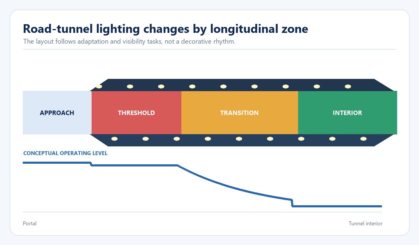
FHWA guidance describes a sequence that includes the approach, threshold, transition and interior zones, with exit conditions also considered. The approach is the open road before the portal, where the tunnel increasingly fills the driver’s view. CIE defines the threshold as the first tunnel section after the portal; FHWA further explains that the threshold begins at the entrance or an installed sunscreen and extends at least through the relevant stopping distance.
The transition follows, reducing luminance in stages as vision adapts. The interior is the longer region where the driver’s eyes have adapted to the tunnel level. Exit treatment depends on direction, daytime and nighttime conditions and the governing design method.
These zones explain why a single constant output is a poor design assumption. The entrance challenge can dominate daytime power, while nighttime conditions require a different relationship with the exterior road.
| Zone | Primary visual task | Design inputs that change the arrangement |
|---|---|---|
| Approach | Let the driver see the portal scene and prepare for entry | Portal surroundings, direction, speed and stopping sight distance |
| Threshold | Maintain obstacle visibility while the driver remains adapted to the exterior | Approach luminance, target contrast, pavement, traffic and governing method |
| Transition | Reduce luminance at a rate compatible with adaptation | Speed, adaptation curve, zone length and control steps |
| Interior | Maintain guidance and object visibility after adaptation | Tunnel length, traffic, geometry, surfaces and maintained condition |
| Exit-related condition | Manage the view toward daylight and the road beyond the portal | Direction, daylight, geometry and the applicable design method |
Why the Entrance Needs Special Treatment
From a bright approach, a poorly lit portal can appear as a dark opening. Objects inside may have insufficient contrast to be detected at the required distance. The threshold system is designed from the outside scene, portal surroundings, traffic and stopping requirement—not from a generic indoor illuminance target.
Tunnel orientation matters. Low sun, sky visible around the portal, snow or bright surfaces can raise the driver’s adaptation luminance. Screens, structures and landscaping can change it. A luminance study is therefore stronger than a fixed regional rule of thumb.
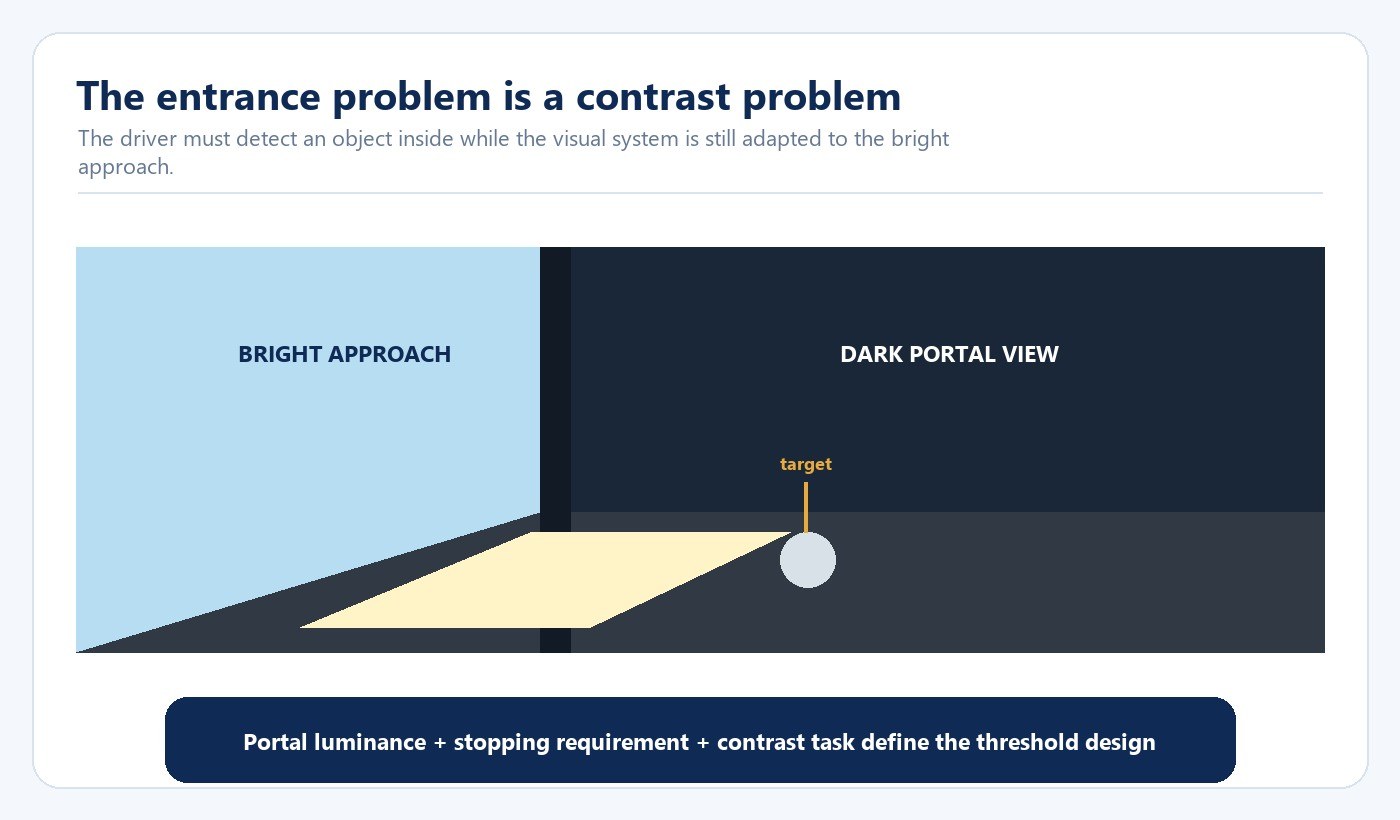
The entrance layout may use more luminaires, higher output, different optics or combinations of base and reinforcement lighting. The exact arrangement follows calculation and photometric files.
Why Output Decreases Through the Transition
Human adaptation from high to low luminance takes time. The transition zone reduces lighting progressively so the driver is not forced into an abrupt change. Its length and steps depend on speed and the allowed adaptation curve in the governing standard.
Visible rows of luminaires may therefore be closer together or operate at higher output near the portal, then become less dense or dim to lower levels. Controls may switch groups in stages as exterior daylight changes. The physical fixture count and operating output are separate design variables.
Abrupt bright-dark bands should be avoided. Uniformity and longitudinal spacing must prevent distracting repetitions, while preserving the target road and wall luminance.
The Interior Zone Is Not “Minimum Light Everywhere”
In the interior, drivers are adapted to lower luminance, but they still need continuous guidance, obstacle visibility and perception of other road users. The required level depends on tunnel length, traffic, speed, wall and pavement properties and standard.
Long tunnels may contain curves, ramps, intersections, lay-bys, signs or equipment areas that need local treatment. A simple equal-spacing line cannot account for every conflict point. Maintenance access and emergency egress also influence positions.
Wall luminance can improve visual guidance and perceived openness. Dirt on walls, pavement and luminaires changes the maintained condition, so design values need realistic maintenance factors and cleaning plans.
Transverse Position and Optical Distribution
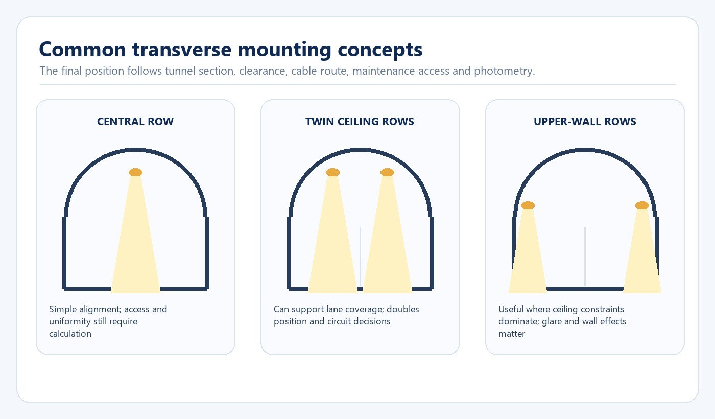
Luminaires may be mounted centrally, in one or more ceiling rows, at upper walls or in other project-specific positions. The choice depends on tunnel section, lanes, clearance, cable routes, maintenance access and the optical distribution.
Symmetric optics distribute light broadly in both longitudinal directions. Counter-beam systems direct a stronger component toward approaching traffic and can create useful object contrast under suitable conditions. Neither is universally best. Pro-beam, symmetric and counter-beam concepts interact differently with pavement reflectance, target contrast, glare and daylight penetration.
Use the exact IES or LDT file in the tunnel calculation. Nominal lumens and beam angle cannot establish road luminance, uniformity or disability glare.
Spacing Comes from Photometry and Geometry
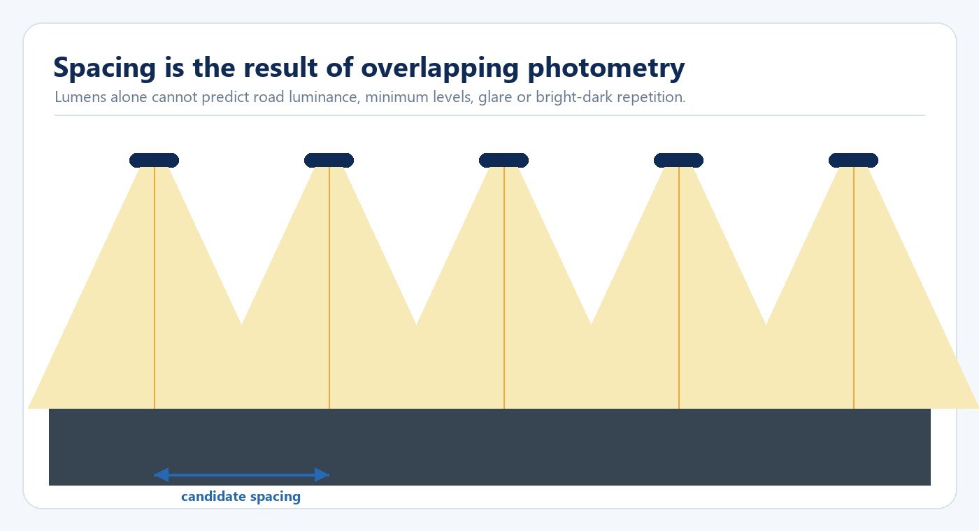
Luminaire spacing is a result, not a starting constant. Mounting height, lateral position, optics, tilt, road width, surface reflectance and target uniformity determine how distributions overlap. Wider spacing may reduce equipment count but create bright-dark patterns or insufficient minimum luminance.
Calculate each relevant zone and operating state. Review average and minimum road luminance, longitudinal and overall uniformity, wall illumination, glare and target visibility as required by the governing standard. Check curves and grade changes separately.
Do not use an illuminance grid alone if the applicable method is luminance-based. The driver’s view of reflected light and contrast is central to tunnel design.
The same evidence discipline applies when comparing project samples. The LED lighting sample evaluation checklist separates identity, test setup and acceptance criteria before different offers are ranked.
Daylight Controls Change the Operating Arrangement
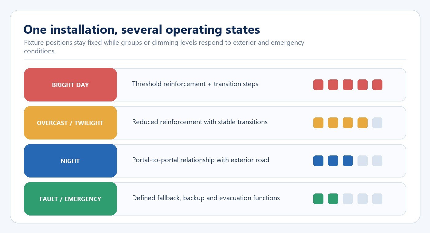
Exterior luminance can vary rapidly with weather and time of day. A tunnel control system may use portal luminance sensors, schedules and staged or continuously dimmed groups to maintain the designed relationship. Sensor placement and cleaning are therefore part of performance.
Define day, twilight, night, maintenance and failure states. Prevent rapid hunting between levels and ensure transitions remain acceptable when a sensor or communication link fails. Commission every state with measured field conditions.
Energy savings should come from controlled reduction within the approved design, not from disabling entrance reinforcement or creating abrupt steps.
Driver and controller evidence should cover every operating state. The LED flicker, power factor and THD buyer guide explains why optical modulation and electrical input measurements must remain separate.
Emergency, Redundancy and Maintenance
Tunnel lighting overlaps with emergency lighting, evacuation, traffic control, fire-life-safety and backup power. The required emergency arrangement is governed by the project and jurisdiction and should not be inferred from normal-lighting rows.
Group circuits so one failure does not create a dangerous dark section. Consider driver and communication failure, cable damage, loss of supply and luminaire maintenance. Access strategy can influence mounting positions because lane closures in tunnels are costly and risky.
Photometric maintenance includes cleaning luminaires and tunnel surfaces, tracking lumen depreciation and verifying sensors. The streetlight driver reliability guide provides a related framework for input protection, driver derating and change control in high-duty outdoor infrastructure. The calculation should represent the maintained condition rather than only initial output.
What a Luminaire Supplier Should Provide
Request exact photometric files, lumen output, power, CCT, CRI, glare data, ingress and impact ratings, ambient limits, driver and control interfaces, surge evidence, lumen-maintenance basis, mounting details and change notification. The project lighting selection framework can be used to organize those inputs before a sample comparison. Data must identify the tested product configuration.
The project designer then combines those files with geometry, reflectance, portal luminance, speed and standard criteria. A supplier should not promise compliant spacing before receiving these inputs.
Manufacturing review may also need to confirm the exact driver, optics, sealing, mounting hardware and change-control boundary; see New Lights factory and manufacturing capabilities.
For a bounded discussion, contact New Lights with the tunnel section, length, direction, speed, portal study, governing standard, control concept and required photometric format.
Frequently Asked Questions
Why are more tunnel lights installed near the entrance?
Daytime entrance lighting supports visibility while drivers adapt from a bright exterior. The required reinforcement depends on portal and traffic conditions.
What are threshold and transition zones?
The threshold begins after the entrance and covers the critical initial distance. The transition then reduces luminance progressively toward the interior level.
Is counter-beam lighting always better?
No. Its value depends on target contrast, pavement, geometry, glare and daylight conditions. Compare calculated systems.
Can tunnel spacing be selected from lumens alone?
No. Exact photometry, mounting, geometry, reflectance, uniformity and luminance criteria determine spacing.
Are tunnel lights dimmed during the day?
Many systems adjust groups or output according to exterior luminance and operating state, but the strategy must be designed and commissioned.
Does normal tunnel lighting provide emergency lighting?
Not automatically. Emergency and backup requirements are separate project and jurisdictional obligations.
Editorial Sources
- Federal Highway Administration, 2023 FHWA Lighting Handbook
- Federal Highway Administration, Roadway Lighting Resources
- CIE, Threshold zone, road tunnel — CIE S 017:2020 e-ILV
- CIE, Guide for the Lighting of Road Tunnels and Underpasses, 2nd ed.
- CIE, Calculation of Tunnel Lighting Quality Criteria