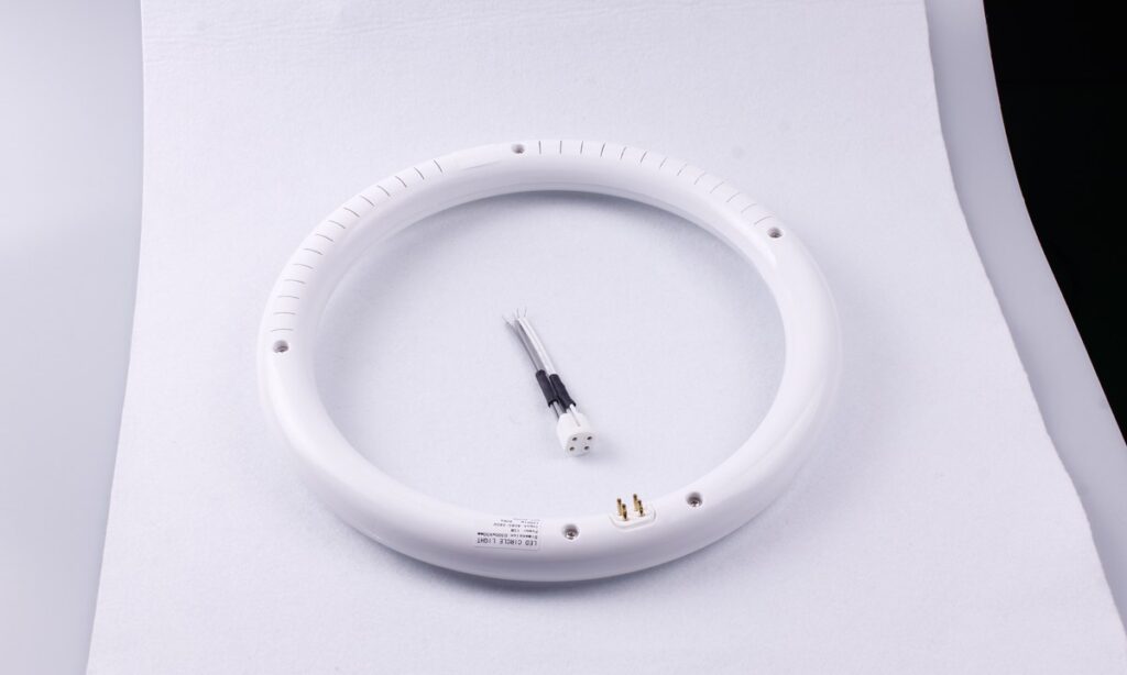
An LED panel light is not made in one operation. The finished luminaire brings together an LED board, optical layers or lenses, a frame or housing, a driver, wiring, connectors and mounting parts. Manufacturing has to keep those elements aligned with the approved design while controlling electrical safety, light distribution, color, thermal behavior and mechanical fit.
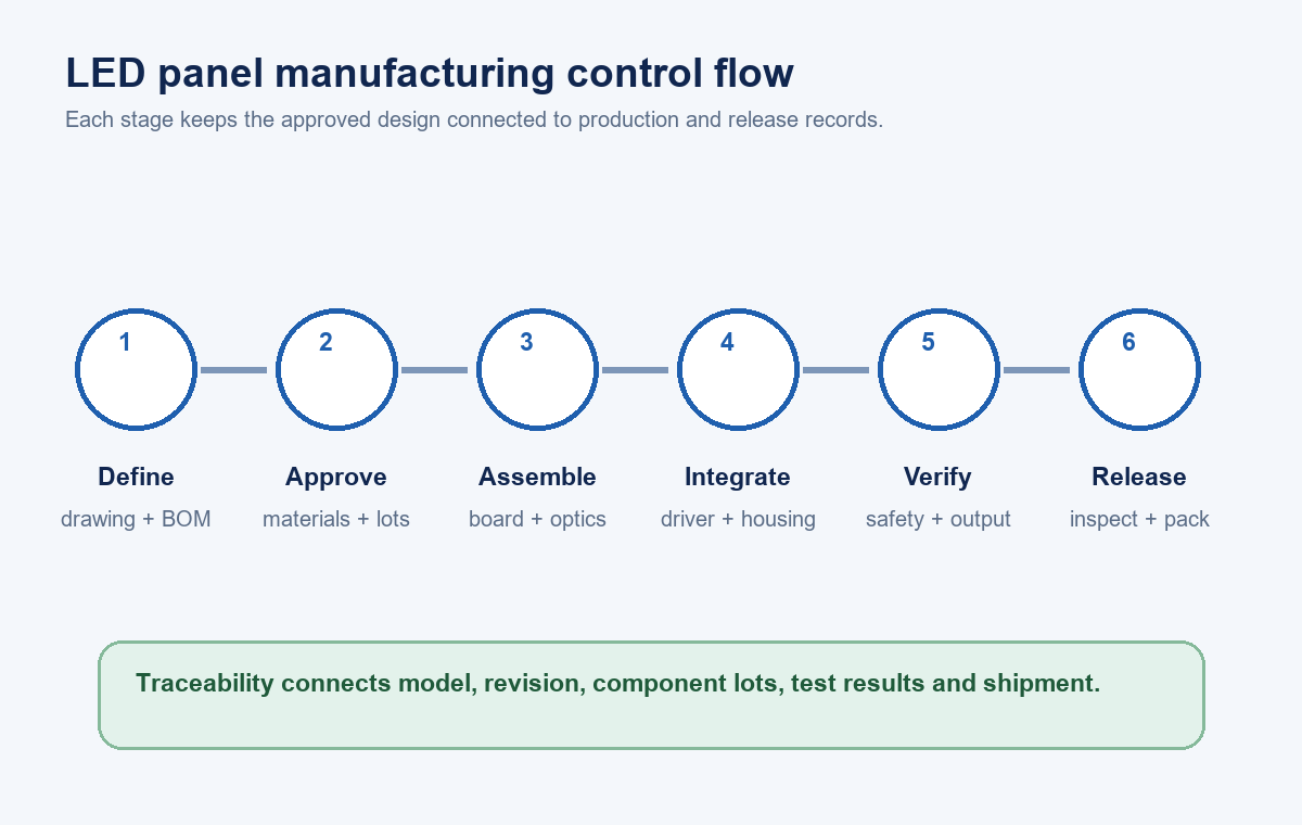
The sequence varies with the construction. Edge-lit panels guide light from LEDs mounted around the perimeter; back-lit panels place LED modules behind the diffuser; slim recessed panels and surface-mounted panels add different housings and installation hardware. Even so, a useful factory-control path is consistent: define the product, approve materials, assemble controlled subassemblies, complete the luminaire, test it against the specification, preserve traceability and release only accepted units.
1. Freeze the Product Definition Before Production
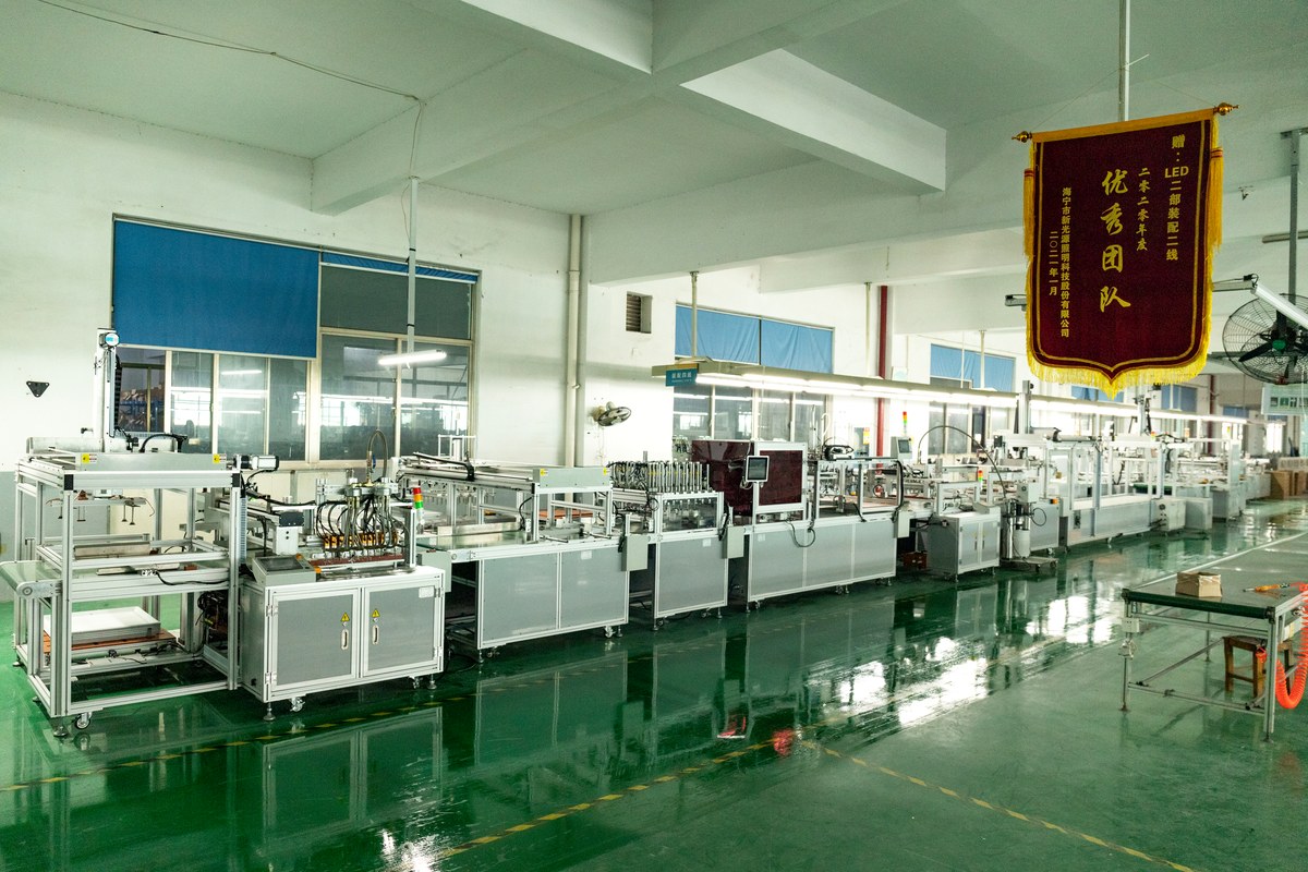
Manufacturing starts with a controlled product definition, not with loose parts on a line. The drawing and bill of materials should identify the panel dimensions, construction, LED board, optical stack, housing, driver, cable, connector, mounting method, label and packaging. The specification should also define rated input, wattage, lumen and color targets, dimming or emergency options, environmental classification and destination-market requirements.
This step matters because apparently interchangeable components can change the result. A different diffuser can alter transmission and glare. A replacement driver can change flicker, power factor, dimming behavior or thermal loading. A different LED package or board layout can shift lumen output, color and current density. Procurement substitutions therefore need technical review and documented approval before they enter a production batch.
Readers who need a component-level introduction can first review what an LED panel light is and how its main designs differ. Buyers comparing available formats can also browse the New Lights LED panel light range and use the separate guide to choose LED panel lights for commercial projects.
| Controlled input | What should be fixed | Typical production risk if it drifts |
|---|---|---|
| Mechanical drawing | Outside size, thickness, holes, tolerances and mounting interfaces | Poor ceiling fit, frame gaps or assembly interference |
| Bill of materials | Approved manufacturer, part number and revision | Unreviewed electrical, optical or thermal change |
| Electrical specification | Input, power, driver output and control interface | Incorrect loading, unstable operation or control mismatch |
| Optical specification | Flux, CCT, color tolerance, CRI and distribution | Visible batch inconsistency or missed project target |
| Compliance file | Applicable construction, markings and critical components | Product no longer matches the assessed configuration |
| Packaging specification | Protection, labels, quantity and carton marks | Transit damage, misidentification or receiving delays |
2. Control Incoming Materials and Critical Components
Incoming control should focus on the components most capable of changing safety, performance or assembly. Depending on the model, that may include LED packages or populated boards, drivers, terminal blocks, internal wiring, insulation, diffusers, light-guide plates, reflective sheets, metal frames, back plates, fasteners and suspension or recessed-mounting parts.
The receiving team can check supplier identity, part number, revision, quantity, appearance, key dimensions and required documentation. Sampling plans should be defined rather than improvised at the dock. Critical electrical components may require confirmation against the approved component list. Optical materials should be protected from dust, scratches, moisture and incorrect stacking because surface damage becomes visible after illumination.
Lots should receive a traceable identity that follows them into production. If a later test identifies a problem, that lot reference helps isolate affected material without treating every unit as identical.
3. Prepare the LED Board and Electrical Subassembly
Some factories receive completed LED boards; others assemble boards through surface-mount production. Where SMT is used, solder paste printing, component placement and reflow settings are controlled for the board design. Inspection can identify missing, reversed, shifted or poorly soldered components before the board is built into the luminaire.
The completed board may then receive electrical and illumination checks. The objective is to find assembly defects early, when the board is still accessible. The test limits should match the product design and should not be replaced by a simple visual judgment that the LEDs turn on.
Driver preparation follows the approved electrical configuration. Leads, connectors, strain relief, earthing parts and insulation systems must remain consistent with the drawing. For a configurable product family, clear routing and labeling are needed so that wattage, CCT, dimming and emergency variants do not become mixed on the same line.
4. Build the Optical and Mechanical System
Edge-lit and back-lit products use different optical arrangements. An edge-lit panel commonly combines perimeter LEDs, a light-guide plate, reflective material and a diffuser. A back-lit panel distributes LEDs across the rear of the optical cavity and uses lenses or a diffuser to control spacing and uniformity. The layer order, orientation, surface condition and distance between parts all influence the visible result.
Operators should handle optical components with clean gloves and protected work surfaces. Dust, fingerprints, scratches and trapped film can cause bright points, shadows or cosmetic rejects. Protective films also need a defined removal stage; leaving the wrong film in the optical stack can reduce output or create visible defects.
Frames, housings and back plates are checked for dimensions, finish, flatness and fastening points before or during assembly. Mechanical tolerances affect more than appearance. They control diffuser retention, board spacing, driver placement, cable clearance and compatibility with ceiling grids, brackets or suspension kits.
5. Complete the Luminaire Assembly
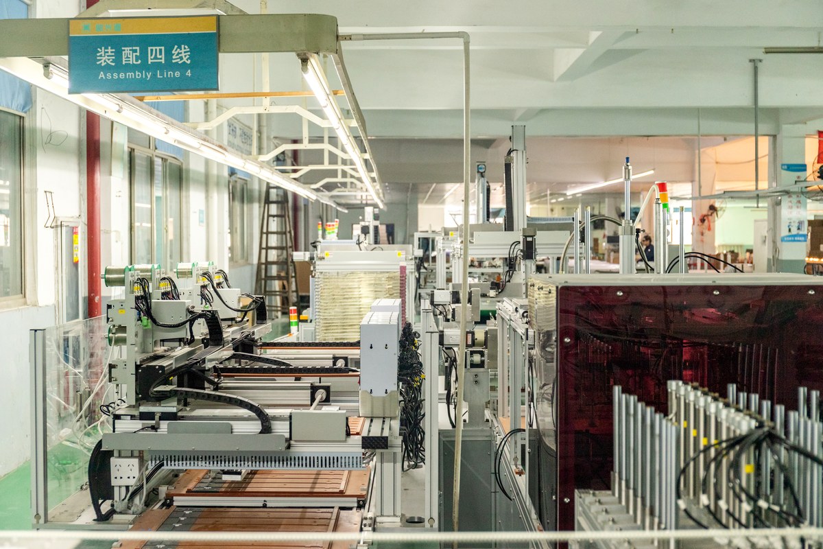
Final assembly integrates the electrical, optical and mechanical sections. The exact order depends on the model, but it normally includes locating the LED board, installing the optical layers, closing the frame or housing, routing wires, connecting the driver, applying insulation and strain relief, fitting mounting accessories and attaching the product label.
Work instructions should show connector orientation, fastener type, torque or fastening method where relevant, cable path and inspection points. Fixtures or poka-yoke features can reduce orientation errors, while barcode or traveler records can connect the finished unit to its material lots and production date.
Variant control is especially important when several visually similar panels share a line. A 0–10 V driver, DALI driver, emergency pack or selectable-wattage version can look nearly identical after the housing is closed. Scanning, separate work orders and final label checks help prevent a correct assembly from receiving the wrong identity.
6. Test Safety, Electrical and Optical Performance
Testing should be selected from the product specification, destination market, certification file and factory control plan. IEC 60598-1 covers general luminaire requirements and tests, including classification, marking, mechanical and electrical construction, while North American projects may involve standards such as UL 1598 and requirements for LED equipment used in lighting products. The applicable edition and certification route should be confirmed for the actual market.
Production-line safety checks may include protective-earth continuity, dielectric strength or polarity where the construction and program require them. Electrical checks can compare input power, current, power factor and operating behavior with the approved limits. A functional check should confirm that the intended version starts, remains stable and responds correctly to its control interface.
Optical verification is a separate task. ANSI/IES LM-79-24 provides procedures for standardized optical and electrical measurements of solid-state lighting products, including luminous flux, intensity distribution, chromaticity and reporting. Routine production screening and formal laboratory measurement serve different purposes: the control plan should define which characteristics are checked on every unit, by batch sampling or during qualification.
| Verification point | Question it answers | Record a buyer can request |
|---|---|---|
| Visual and dimensional inspection | Is the product complete, clean and within drawing tolerances? | Inspection criteria and batch result |
| Grounding or dielectric check where applicable | Does the assembled electrical construction meet the required production test? | Test method, limit, equipment ID and result |
| Input power and operating current | Does the built unit match its electrical specification? | Sample or line-test record by model and batch |
| Luminous flux and efficacy | Does measured output meet the declared target under stated conditions? | Laboratory report with model identity and conditions |
| CCT, chromaticity and CRI | Is color controlled within the project requirement? | Color data and acceptance tolerance |
| Distribution and uniformity | Does the panel produce the intended optical pattern? | Photometric report or approved comparison method |
| Dimming, sensor or emergency function | Does the configured variant operate with its specified interface? | Functional test record for the exact variant |
7. Use Thermal and Reliability Evidence at the Right Stage
A brief switch-on test cannot establish long-term performance. Product development and qualification may therefore include thermal measurements, abnormal-condition checks, switching cycles, endurance work, environmental exposure or component-level reliability evidence. The program should reflect the construction, intended environment, declared ratings and market requirements.
Thermal review is important because LED output, color, driver life and material behavior are temperature dependent. Measurement locations and limits need to come from the design and compliance plan. A temperature reading without a defined location, ambient condition, stabilization method and acceptance limit is difficult to compare across samples.
When evaluating a supplier, ask how qualification evidence connects to the production model. The model code, driver, LED board, housing, optical system and revision should be identifiable. If a critical part changes, the change-control process should decide what review, testing and customer communication are required.
8. Inspect, Pack and Release the Batch
Final inspection confirms product identity and workmanship before packaging. Typical checks include label accuracy, surface condition, frame fit, accessories, protective film, cable and connector condition, operating function and carton contents. The accepted sample and work instruction should define cosmetic limits so that decisions remain consistent between shifts and batches.
Packaging must protect the diffuser, corners, frame and accessories through stacking and transport. The carton label should match the product and purchase order, while inner protection should prevent movement and surface contact. For mixed variants, carton-level identification is essential because the product may not be distinguishable after palletization.
Release records can connect the purchase order, model, revision, production date, quantity, inspection result and material or test references. Buyers can use the LED lighting sample evaluation checklist to establish an approved reference before mass production, then align receiving checks with the same model and evidence. The LED product compliance document checklist helps organize the documents that should travel with the commercial decision.
What Buyers Should Confirm During a Factory Review
A factory tour is most useful when it follows one current model from controlled inputs to release records. Start with the approved drawing and bill of materials, then compare them with the work order, line materials, label, test limits and packaged unit. This reveals whether the process maintains product identity instead of simply showing available equipment.
Ask how incoming lots are identified, how substitutions are approved, how variants are separated, how test equipment is maintained, how failed units are contained and how corrective actions are closed. Review one traceability example in both directions: from a finished carton back to its production and material records, and from a component lot forward to the finished batches that used it.
For a broader view of New Lights’ production and project-support capabilities, visit Factory & Manufacturing. To discuss a panel-light specification, sample plan or OEM/ODM requirement, contact the New Lights team with the target market, installation format, quantities and required documents.
Frequently Asked Questions
What are the main stages of LED panel light manufacturing?
The usual control stages are product definition, incoming-material approval, LED board and electrical preparation, optical and mechanical assembly, final integration, safety and performance testing, final inspection, packaging and batch release.
Are edge-lit and back-lit LED panels manufactured the same way?
No. They share electrical, mechanical and quality controls, but the optical construction differs. Edge-lit panels use perimeter LEDs and a light-guide system, while back-lit panels place LEDs behind the diffuser, often with lenses to shape distribution.
Is a switch-on test enough for final inspection?
No. It confirms basic operation but does not cover product identity, electrical safety, input characteristics, color, lumen output, distribution, dimensions, controls or required documentation. The acceptance plan should define the checks for the exact model and market.
What manufacturing records should a buyer request?
Useful records include the controlled drawing and bill of materials, approved-component list, incoming inspection, production traveler or batch identity, test results, calibration status, final inspection and change-control history. The required set depends on the project and compliance route.
How should a buyer evaluate a proposed component substitution?
Compare the proposed part with the approved part for electrical, optical, thermal, mechanical and compliance effects. Record the review, required re-testing, customer approval and revision change before the substitute enters production.