Beam angle describes how a fixture sends light away from its optical center, but it does not determine a layout by itself. For a T8 integrated LED fixture, use the angle as an early indication of spread, then review the exact model’s luminous-intensity distribution or IES file together with lumens, mounting height, orientation, surface reflectance and the task plane. Confirm the result in a calculation and a representative sample before fixing the spacing.
This distinction matters because two linear fixtures can carry a similar headline beam angle yet produce different center intensity, end distribution, glare and overlap. The practical question is not simply whether the beam is wide or narrow. It is whether the complete distribution suits the shelves, counters, worktops, aisles or vertical faces that must be illuminated.
What Beam Angle Tells You—and What It Does Not
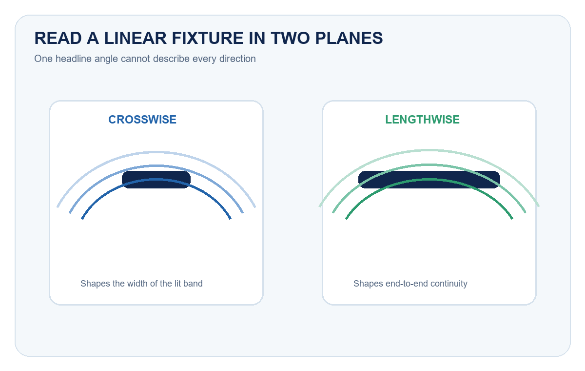
Beam angle is commonly defined from the directions where intensity falls to a specified fraction of the peak, often half of the maximum intensity. CIE provides a repeatable method for determining the optical beam axis, center-beam intensity and beam angle. For a non-symmetrical source, more than one beam angle may be needed because distribution across the fixture can differ from distribution along it.
A linear fixture therefore should not be reduced to one circular cone. Its crosswise spread influences the width of the lit band, while its lengthwise distribution affects end-to-end continuity. The lens, housing, LED-board position and mounting orientation all contribute to the actual candela pattern.
| Input | What it helps predict | What it cannot confirm alone |
|---|---|---|
| Beam angle | General spread and likely overlap tendency | Illuminance, uniformity, glare or end distribution |
| Candela curve or IES file | Intensity by direction for the tested fixture | Performance after an unverified product or orientation change |
| Delivered lumens | Total light leaving the fixture | Where that light reaches the room |
| Mounting height | Beam footprint and distance-related intensity | Obstructions, reflectance or exact task-plane result |
| Spacing and orientation | How adjacent distributions overlap | Acceptance without a calculation or field check |
| Surface reflectance | Contribution from walls, ceiling, shelves and finishes | The direct distribution of the fixture itself |
Use the IES File for Layout Decisions
The Illuminating Engineering Society describes an IES file as a standardized digital representation of a light source’s distribution. It records candela values at defined angles and allows lighting software to model how an identified fixture behaves in a space. This is more useful for layout than a single angle printed in a summary table.
Ask for the photometric file that matches the exact length, wattage, optical configuration and test orientation being considered. Check the report or file header for the tested model and source information. A family-level brochure or a file from another length may be useful for early discussion, but it is not model-level evidence for a final calculation.
If no matching file is available, treat the layout as provisional. A physical sample can reveal visible bands, end shadows and glare, but an informal photograph cannot replace calibrated photometry. The LED lighting sample evaluation checklist provides a consistent way to record the sample identity and acceptance conditions.
Mounting Height Changes the Footprint
Moving a fixture farther from the target usually enlarges the illuminated footprint and reduces direct intensity at the surface. Moving it closer can increase local intensity but make bright and dark bands more visible. These tendencies are useful for initial reasoning, yet reflected light, linear end effects and non-uniform intensity mean that a simple cone calculation is only an approximation.
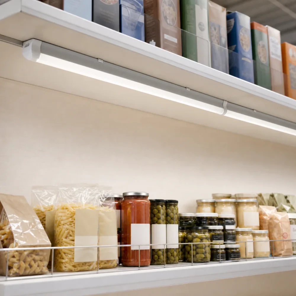
For under-shelf lighting, the short distance between fixture and merchandise can make individual bright bands obvious. A wider crosswise distribution can improve coverage, while shielding and placement near the front or rear edge change how much light reaches labels and vertical faces. For higher mounting positions, output, spacing and room geometry become increasingly important.
The New Lights surface-mounted T8 integrated LED fixture combines the source, driver, diffuser and housing in a compact linkable form. Its product page is a useful reference for the available physical format and installation accessories. Request model-level photometry separately when the project decision depends on distribution.
Plan Overlap Instead of Chasing One Spacing Ratio
Uniformity comes from controlled overlap between adjacent distributions. Too little overlap can create dark bands. Excessive overlap may waste light, raise local brightness or expose glare without improving the target surface. Because the relevant target can be horizontal, vertical or both, spacing should be measured against the actual task—not only the ceiling grid.
Start with the architectural dimensions, then place the exact photometric file in a lighting calculation. Review average and minimum illuminance, uniformity, vertical illuminance where relevant and high-angle intensity at normal viewing positions. If the space contains shelves, beams, ducts or deep equipment, model or test those obstructions as well.
The prismatic lens and linear-light uniformity guide explains how a lens changes brightness transition and visual continuity. For projects where UGR, color quality or temporal light modulation is the primary concern, use the separate UGR, CRI and flicker guide rather than treating beam angle as a substitute for those metrics.
Match the Distribution to the Application
Different spaces reward different distributions. Retail shelving often needs light on vertical packages and labels. Worktops need useful horizontal illuminance without a bright source in the user’s field of view. Aisles need continuity along the travel direction and enough vertical light for racks or signs. Display coves may prioritize visual gradient and concealment over high task illuminance.
| Visible result | Likely variables to check | Useful next action |
|---|---|---|
| Bright stripe directly below the fixture | Very short mounting distance, narrow crosswise distribution or high center intensity | Test a wider distribution, increase distance or adjust lateral position |
| Dark band between rows | Spacing too large for the mounting height and actual candela pattern | Recalculate overlap or add/reposition a row |
| Dim fixture ends | Lengthwise falloff, connector gap or fixture placement | Review longitudinal curve and end-to-end spacing |
| Labels or rack faces remain dark | Layout optimized only for a horizontal plane | Add vertical calculation points and adjust aiming or position |
| Source appears harsh at normal viewing angles | Exposed high-angle intensity, insufficient shielding or reflective surfaces | Review glare from observer positions and test the complete assembly |
| Good sample result but poor rollout consistency | Different model, optic, orientation, spacing or surface condition | Lock the approved configuration and inspect representative zones |
For retail, the New Lights commercial and retail lighting solution shows the wider application context, while the lighting zones, optics and controls guide connects distribution to merchandise and circulation zones. For warehouses, the warehouse lighting RFQ checklist helps define racks, aisles, controls and validation before suppliers quote.
Check Orientation and Installation Details
An IES file represents a tested orientation. Rotating a non-symmetrical fixture can rotate the distribution relative to the room. Surface mounting, corner mounting and mounting under a shelf can therefore produce different practical results even when the product is unchanged.
Record which face is down, the connector direction, distance from the shelf edge, distance to the target, row spacing and any nearby lip or fascia. Make sure accessories do not twist the fixture or change its location between the sample and the rollout. If fixtures link end to end, include connector gaps and feed positions in the visual review.
DOE guidance on LM-79 reports notes that light distribution is part of photometric testing and that test orientation matters. Use the report and matching IES data for the configuration being specified. If the installation orientation differs, ask whether additional data or a representative test is needed.
Build a Representative Mock-Up
A mock-up should reproduce the difficult parts of the real application: deepest shelf, darkest finish, most reflective package, longest fixture gap, typical observer position and any fascia that can block the beam. Evaluate the installation after ambient light and controls are set to their intended conditions.
Record illuminance at agreed points rather than relying only on a phone camera. Also inspect the visual transition between fixtures, labels near shelf edges, reflections on glossy products and source visibility from standing and seated viewpoints. The commercial LED retrofit guide explains how to carry a verified sample into a controlled rollout.
RFQ Information to Request
Include enough information for every supplier to evaluate the same problem. Provide drawings, mounting height, target planes, required illuminance and uniformity, surface finishes, obstructions, controls and expected operating conditions. Ask the supplier to identify the proposed model rather than answering only with a product family.
Request the matching datasheet, IES file and relevant photometric report. State whether alternatives may change length, wattage, diffuser, LED board, mounting orientation or spacing. If an alternative is offered, require the calculation and sample record to be updated. This prevents a visual sample from becoming approval for a different production configuration.
For each approved area, retain the model, revision, optical configuration, mounting detail, spacing, control state and acceptance measurements. Add these records to the lighting maintenance and spare-parts plan so replacement units preserve the intended distribution.
A Practical Decision Sequence
- Define every horizontal and vertical surface that needs useful light.
- Record mounting height, orientation, spacing limits, finishes and obstructions.
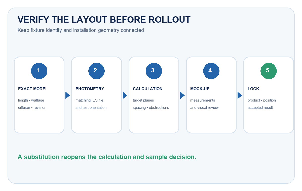
- Identify the exact fixture length, wattage, diffuser and accessories.
- Obtain the matching IES file and review both distribution planes.
- Calculate illuminance, uniformity and relevant observer positions.
- Build a representative mock-up and record measurements and visual observations.
- Lock the accepted product and installation configuration before rollout.
If you have drawings and application dimensions, contact New Lights with the target surfaces, mounting details, quantity and required documentation. The team can review whether the current product format is a reasonable candidate and identify what model-level evidence is still needed.
Frequently Asked Questions
Does a wider beam angle always create better uniformity?
No. A wider distribution can improve overlap at short spacing, but output, center intensity, mounting height, obstructions and surface reflectance still affect uniformity. Use the exact photometric file and test the real geometry.
Can beam angle determine fixture spacing?
It can support an early estimate, but it should not set final spacing alone. Final spacing should come from a calculation using the exact fixture distribution and a representative field check.
Why can two fixtures with the same beam angle look different?
The same headline angle can hide different candela shapes, peak intensities, lengthwise distributions, lens appearances and total output. Compare complete photometric data and samples, not only one number.
Do I need an IES file for under-shelf lighting?
It is strongly useful when uniformity, vertical illumination or repeatable rollout matters. For a small decorative installation, a measured mock-up may carry more of the decision, but the exact product and mounting configuration should still be recorded.
What should be approved after the mock-up?
Approve the exact model, optical configuration, orientation, mounting position, fixture spacing, control state and measured acceptance result. A photograph by itself is not a complete approval record.
Editorial Sources
- International Commission on Illumination (CIE), The Determination of the Optical Beam Axis, Centre Beam Intensity and Beam Angle(s) of Directional Light Sources: https://cie.co.at/publications/determination-optical-beam-axis-centre-beam-intensity-and-beam-angle-directional-light
- Illuminating Engineering Society, Learn About IES Files: https://ies.org/education/learn-about-ies-files/
- U.S. Department of Energy, A Practical Primer on LED Technology: https://www.energy.gov/management/articles/practical-primer-led-technology