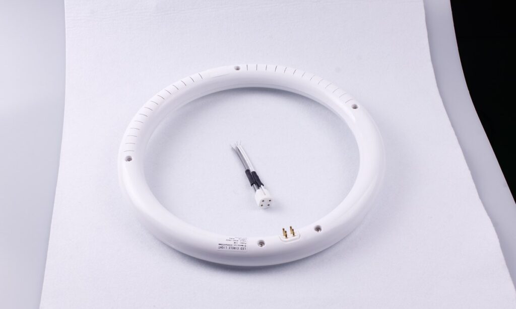
A microwave sensor LED bulb may switch on unexpectedly when its installed detection zone reaches movement outside the area that should control the light. Reflections, partitions, mounting position and sensitivity can all change that zone. The practical fix is to identify the triggering event, map the boundary, adjust one variable at a time and then check that valid occupants are still detected.
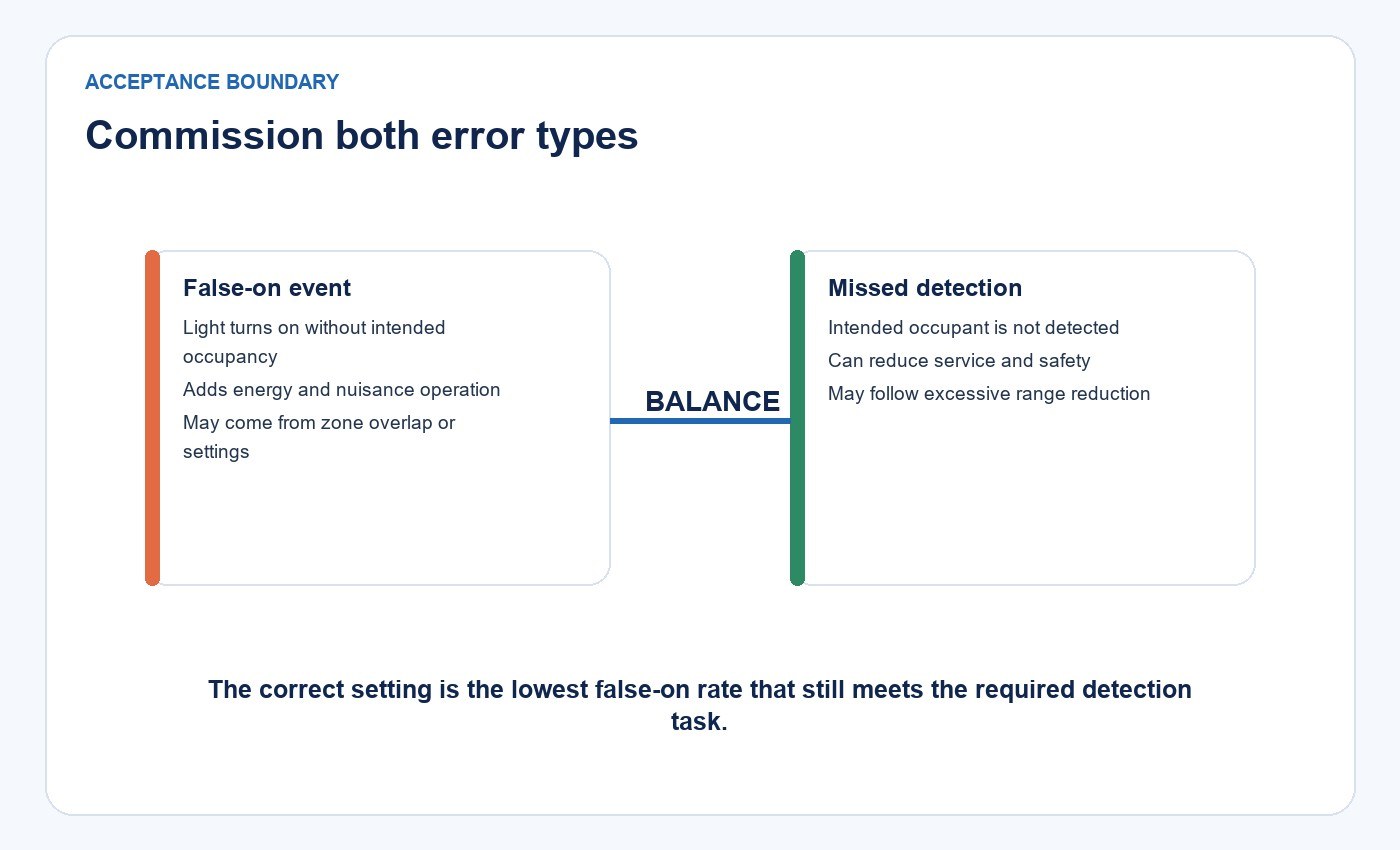
Reducing false-on events is only half of the job. A setting that prevents unwanted activation but misses a person, or switches off while the space is occupied, is not a successful result. Commissioning must balance both error types under the actual installation conditions.
Define the Event Before Changing Settings
“False trigger” is often used for several different complaints. Separate them before diagnosing the installation.
| Observed event | Expected light response | Classification | What to investigate first |
|---|---|---|---|
| A person moves inside the intended zone | The light enters the occupied state | True detection | Response time and coverage |
| The intended zone is vacant | The light remains in its unoccupied state | True non-detection | Baseline behavior |
| Movement occurs outside the intended zone and the light changes state | The light should ignore the event | False-on event | Zone boundary, reflections and sensitivity |
| A person moves inside the intended zone and the light does not respond | The light should respond within the agreed time | Missed detection | Blind spots, orientation and sensitivity |
| The light dims or switches off while a person remains present | The occupied state should continue | Premature shutoff | Small-motion coverage and hold time |
The Illuminating Engineering Society defines an occupancy sensor by its control function: it detects presence, controls equipment and switches it off after a preset period without detected presence. U.S. Department of Energy FEMP guidance likewise treats application, sensor technology, location and control strategy as part of suitability. That sequence makes the delay part of system behavior, not a substitute for adequate detection.
Why the Detection Zone Can Cross a Room Boundary
Microwave sensing responds to changes in returned radio-frequency energy. The resulting zone is affected by the sensor and antenna design, the bulb and fixture construction, mounting orientation, surrounding materials and moving objects. It is not simply a perfect circle described by one radius.
A lightweight partition or doorway may allow relevant signal energy to reach an adjacent route. Metal surfaces can block or redirect energy, while glass, shelving, ducts and equipment can reshape the practical response. Movement direction, target size and speed also matter. This is why a bench test or nominal range cannot predict every installed boundary.
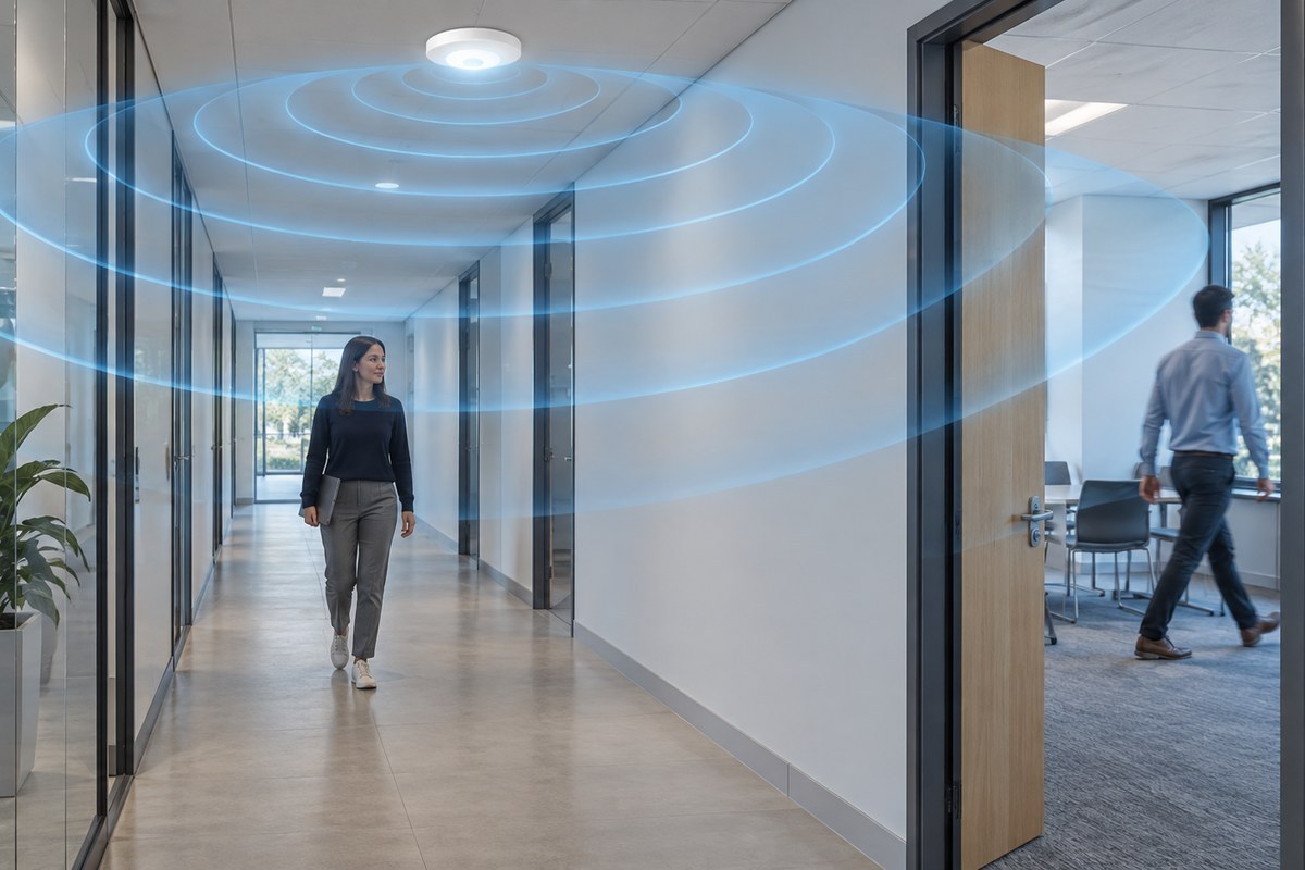
The goal is not maximum reach. It is reliable coverage of valid movement inside the controlled area while rejecting movement that should not change the light state.
Map the Intended Zone and the Likely Trigger
Draw a simple plan and section before touching the settings. Mark the bulb position and orientation, mounting height, intended occupied area, doors, windows, partitions, metal surfaces, moving equipment and nearby circulation routes. Add every event that coincided with an unwanted switch-on.
Then reproduce one suspected event at a time while the intended zone is vacant. Ask someone to walk along the adjacent corridor, open the nearby door, operate the fan or move the equipment. A repeatable trigger is far more useful than an isolated complaint because it gives the next adjustment a defined test.
For the exact product, compare the drawing with its installation instructions and detection diagrams. New Lights lists a verified family of microwave-sensor LED bulbs, but mounting, settings and target-market documentation still need to be checked by exact model rather than inferred from the family name.
Change One Variable at a Time
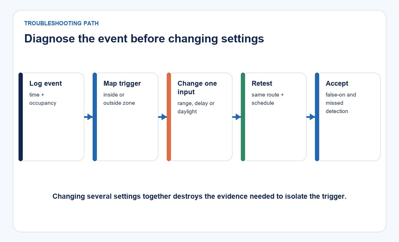
If several variables change together, an apparent improvement cannot be attributed to one cause and may hide a new blind spot. Use a controlled sequence:
- Record the model, revision, mounting, fixture, supply and original settings.
- Establish a baseline with both valid occupancy and unwanted-event tests.
- Select the most likely cause and change one setting or physical condition.
- Repeat the same event set in the same order.
- Compare false-on events, missed detections and premature shutoffs.
- Keep the change only if the combined result improves.
- Record the accepted setting and restore the prior state if performance worsens.
This method also helps distinguish a sensor-zone issue from power cycling, wiring faults, unstable controls or another electrical problem.
Sensitivity Can Trade False-On Events for Blind Spots
Lower sensitivity may reduce responses to distant or weak movement. It can also reduce coverage at the edge of the intended zone or fail to detect small motion. Higher sensitivity can improve difficult coverage while expanding response beyond the target boundary.
Test the hardest valid cases after every sensitivity adjustment: slow approach, movement near the far edge, a person working relatively still and movement partly screened by furniture. If unwanted activation stops but one of these cases fails, the setting has shifted the error rather than solved the installation.
Physical changes may be more effective than continued tuning. Reorientation, a different mounting position, shielding allowed by the manufacturer or a sensor with a more suitable pattern can align the practical zone with the room.
Hold Time Changes Service and Energy Behavior
Hold time determines how long the occupied state continues after the last accepted motion. A longer delay can bridge occasional gaps in small-motion detection, but it keeps the light in a higher-power state after vacancy. A shorter delay can reduce that time while making premature dimming or shutoff more likely.
Lawrence Berkeley National Laboratory guidance on lighting controls emphasizes commissioning and calibration, noting the consequences of sensitivity that is too high or too low and delay settings that are too short. The correct delay therefore depends on the activity, required response and control sequence—not on one universal “best” number.
Corridors, desks, stairs, storage rooms and machine areas have different movement patterns and consequences. Emergency and minimum-light requirements must remain separate from an occupancy-control adjustment.
Test Daylight Control Separately
Some sensor bulbs also use ambient-light input. If that feature exists on the exact model, the control may correctly detect motion but intentionally keep the lamp off above a daylight threshold. That is not missed motion detection.
Near the transition point, test daylight and electric-light conditions separately. Sensor position, reflected light, lamp light reaching the sensor and hysteresis can affect switching. Watch for repeated on-off cycling and inconsistent dawn or dusk behavior.
Do not use a daylight setting to diagnose a spatial false-on event. First determine whether motion was detected and then whether the light-state decision followed the configured daylight rule.
Use a Symptom-to-Test Sequence
| Symptom | Most useful first test | Possible next action | Boundary to protect |
|---|---|---|---|
| Light turns on when someone passes outside the room | Reproduce the adjacent route with the room vacant | Adjust orientation or sensitivity; assess a different pattern | Retest valid movement at the far edge |
| Light switches off while a person is working | Test small motion at the normal working position | Improve coverage or increase hold time | Do not mask a major blind spot with delay alone |
| Light remains on after everyone leaves | Record last valid event and actual timeout | Verify hold time and repeated external triggers | Separate control delay from a stuck state |
| Behavior changes when equipment starts | Repeat the equipment cycle without occupants | Review placement, vibration, reflections and electrical effects | Keep electrical diagnosis separate from zone tuning |
| Motion is detected but the lamp stays off | Repeat at different ambient-light levels | Verify daylight threshold and control sequence | Do not classify intentional daylight suppression as missed detection |
This sequence narrows the next test. It does not assume that every unexpected switch-on has the same cause.
Measure Both Error Types Over Representative Operation
A walk test establishes basic coverage, but intermittent triggers often appear only during normal shifts. For a pilot area, log representative operating periods and record:
- valid occupancy opportunities and true detections;
- missed detections and premature shutoffs;
- vacant observation time;
- false-on count and duration;
- full, standby and off-state time;
- settings, installation state and any environmental change.
Define acceptance criteria before reviewing the result. One useful calculation is missed-detection rate = missed detections divided by valid occupancy opportunities. False-on performance can be reported as events per vacant observation hour and as total false-on duration. Both count and duration matter because one long activation is different from several brief activations.
For example, if a pilot records 40 valid occupancy opportunities with two misses, the missed-detection rate is 5%. If three false-on events occur during ten vacant observation hours, the observed frequency is 0.3 events per vacant hour. These figures describe only that pilot, setting and environment; they become useful when compared with a predefined acceptance limit and a revised configuration tested on the same basis.
For larger controlled-lighting projects, the related guide to connected lighting and controls in commercial specifications explains how control sequences, commissioning and records fit into project requirements. The commercial and retail lighting solution provides the broader application context. Energy calculations for tube-based systems are handled separately in the microwave-sensor T8 energy-savings guide.
Keep Detection Quality and RF Compliance Separate
For the United States, the Electronic Code of Federal Regulations, 47 CFR Part 15, sets equipment-authorization and technical requirements for intentional radiators. The exact authorization route and applicable rule section depend on the device. A market-specific grant, report and label therefore need to match the exact model and operating configuration.
RF compliance does not establish good detection boundaries, and a successful room test does not establish RF, EMC or electrical-safety compliance. Buyers should maintain separate evidence for regulatory status, electrical construction and installed sensor performance.
What Buyers Should Request
Before approving a sensor-bulb application, request the exact model and revision, control sequence, installation limits, detection diagrams, available settings and target-market documentation. The evaluation package should also define false-on, missed-detection and premature-shutoff metrics; state the test conditions and sample size; and preserve raw event counts rather than only a percentage improvement claim.
Where firmware or configurable logic is involved, record its version and change-control process. Where the product is simple and fixed-function, the installation and acceptance test become even more important because field adjustment options may be limited.
Send New Lights the model, room plan, mounting position, intended zone, settings and event log through the contact page when you need a bounded product and application review.
Frequently Asked Questions
Can a microwave sensor bulb eliminate false triggers?
No installation can be assumed to have zero false triggers in every environment. Define the zone, test events and observation period, then evaluate both false-on and missed-detection results.
Why does the bulb turn on when someone walks outside the room?
The installed sensor zone may overlap the adjacent route through a doorway, partition or reflected path. Reproduce the event, then review mounting, materials, orientation and sensitivity.
Should I reduce sensitivity first?
Only after recording a baseline. Lower sensitivity may reduce unwanted activation but can create missed detection at the edge of the intended zone. Retest the hardest valid occupancy cases after the change.
Can a longer delay fix missed detection?
It can hide short gaps by keeping the occupied state active, but it does not repair a major coverage blind spot. Check zone coverage first and use delay to match the activity and service requirement.
Does an FCC authorization prove sensor accuracy?
No. Equipment authorization addresses applicable RF requirements. Detection accuracy and zone behavior require a separate, defined installation test.
Editorial Sources
- Illuminating Engineering Society, occupancy sensor: https://ies.org/definitions/occupancy-sensor/
- U.S. Department of Energy FEMP, Wireless Occupancy Sensors for Lighting Controls: https://betterbuildingssolutioncenter.energy.gov/sites/default/files/attachments/wireless_occupancy_sensor_guide.pdf
- Lawrence Berkeley National Laboratory, lighting-control commissioning guidance: https://eta-publications.lbl.gov/sites/default/files/60606.pdf
- Electronic Code of Federal Regulations, 47 CFR § 15.201: https://www.ecfr.gov/current/title-47/chapter-I/subchapter-A/part-15/subpart-C/section-15.201
- New Lights, Microwave-Sensor LED Bulbs: https://www.new-lights.com/products/led-bulbs/smart-functional-led-bulbs/microwave-sensor-series-led-smd-bulbs/