A T8 LED glass tube should be evaluated as an optical and electrical system, not selected from a claim about glass transmittance alone. Compare the exact lamp’s lumens, input watts, distribution, glare control and wiring method, then test it inside the intended fixture. The winning option is the one that maintains the required light on the task while reducing measured system power and meeting the project’s visual, safety and maintenance requirements.
Glass can provide a stable tubular envelope and can be clear, coated or diffusing. It does not by itself determine efficacy, energy savings or suitability. LED packages, coating, driver losses, thermal conditions, beam distribution, fixture optics and controls all influence the result.
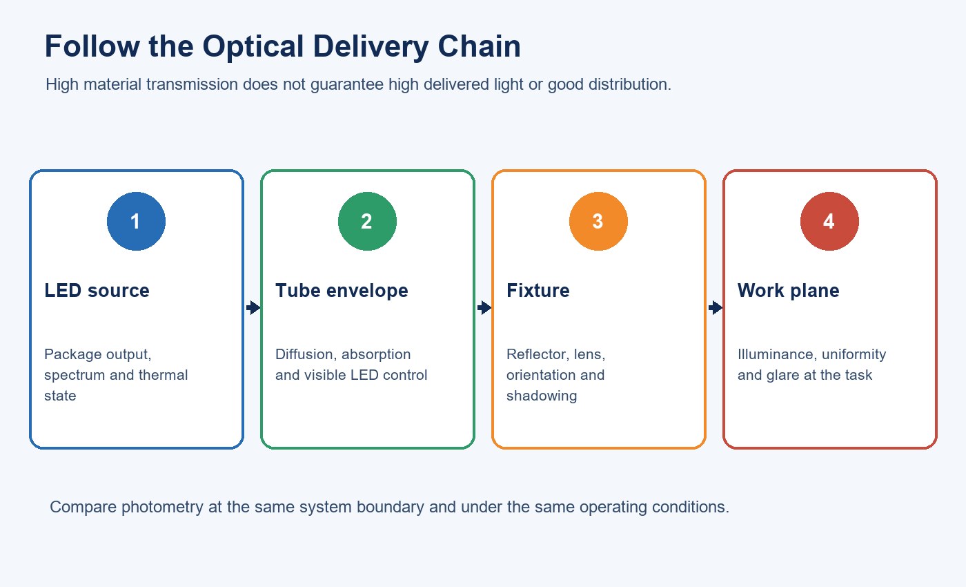
Separate Transmission, Diffusion and Delivered Light
Transmission describes the portion of incident light that passes through a material under stated test conditions. Diffusion describes how that transmitted light is scattered. These are related but different properties: a highly diffusing coating may improve visual uniformity while changing total transmitted flux, and a clearer construction may reveal LED points or produce stronger directional contrast.
The Illuminating Engineering Society defines a diffuser as an optical device that redirects or scatters light primarily through diffuse transmission. That definition describes the optical action; exact-model testing is still needed to quantify output and distribution.
The project’s target is usually neither maximum material transmission nor maximum bare-lamp lumens. It is suitable illuminance and uniformity in the room, with acceptable glare and power consumption. The guide to prismatic lenses and uniformity explains the same distinction at luminaire level: an optical element redistributes light, so it must be judged by the resulting distribution as well as its transmission.
| Optical variable | What it changes | What to verify |
|---|---|---|
| Glass or housing transmission | Flux leaving the tube wall | Exact-model photometric report and stabilized lumens |
| Haze or diffusing coating | LED image, apparent uniformity and beam spread | Lit appearance, intensity distribution and glare from normal views |
| LED-board position | Direction and shadowing inside the tube | Polar distribution and orientation in the lampholder |
| Fixture reflector or lens | Light trapped, redirected or absorbed after leaving the lamp | Complete-fixture output and workplane measurements |
| Surface ageing or dirt | Output and appearance over time | Maintenance plan and representative environmental exposure |
Start with the Exact Product Construction
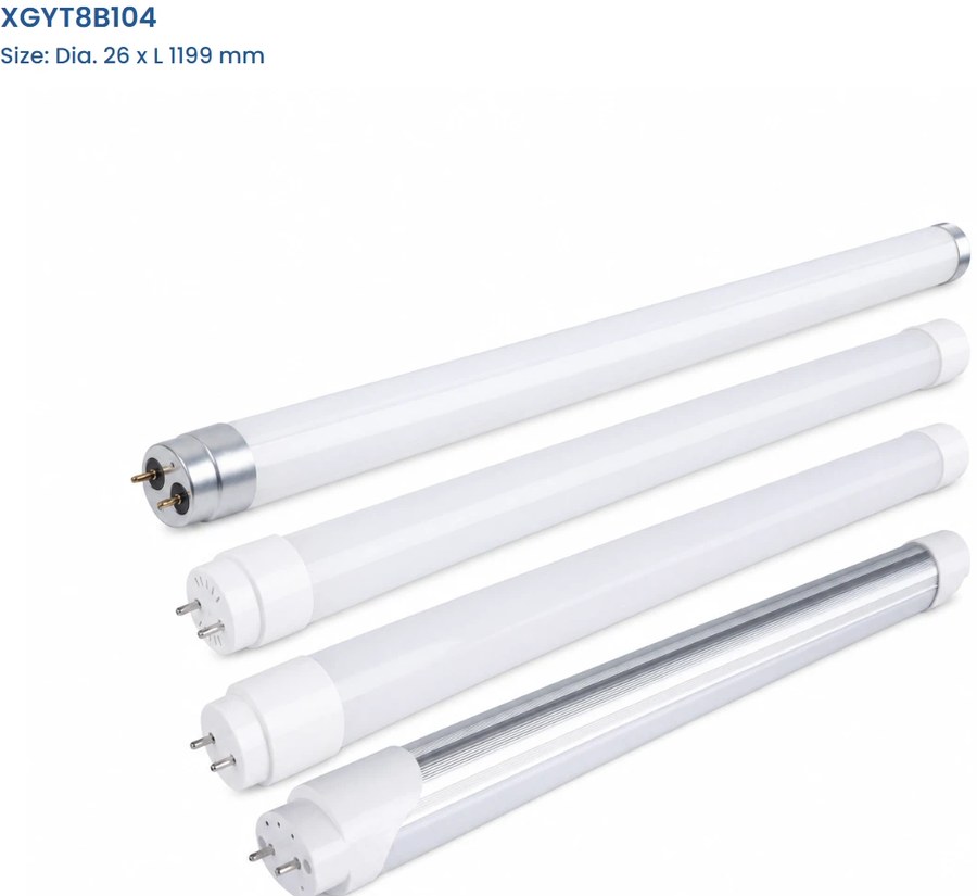
Record tube diameter and length, base, housing material, coating, end-cap construction, electrical input side and permitted operating orientation. Products sharing a T8 shape can use different internal boards, drivers and optical treatments.
The current European T8 LED Glass Tube family uses a 26 mm G13 tubular format and publishes glass, PC, nano-coated and aluminium-plus-PC housing choices. It also uses single-sided electrical input. Those family choices make a useful comparison set, but the ordered model and housing must be identified on the specification, sample and carton label.
Do not transfer one housing option’s appearance or performance to another. A catalogue family may contain several lengths, wattages, end caps and optical constructions. Request model-level data rather than averaging the family.
Read Photometric Data at the Correct Boundary
Before comparing values, identify what was tested. Bare-lamp lumens describe the tube outside the fixture. Complete-luminaire lumens include losses and redistribution from the reflector, lens, louver and housing. Workplane illuminance adds the effects of mounting height, spacing, room surfaces and layout.
These boundaries answer different questions. Bare-lamp data helps compare exact lamps under a common method. Complete-fixture data shows how the selected tube and existing luminaire work together. Field measurements show whether the installation meets the actual task.
| Evidence | Test boundary | Decision it supports | Common misuse |
|---|---|---|---|
| Lamp photometry | Exact tube outside the fixture | Model-level output, efficacy and distribution | Treating bare-lamp lumens as light delivered to the desk |
| Luminaire photometry | Tube installed in a defined fixture | Fixture output, efficiency, distribution and glare review | Applying one fixture result to a different reflector or lens |
| Lighting calculation | Defined room geometry and reflectances | Layout, spacing and predicted illuminance | Using generic inputs instead of the selected lamp and fixture file |
| Site mockup | Actual space, voltage, controls and mounting | Visual acceptance and measured task performance | Testing only the brightest point below one fixture |
Check whether photometric and electrical values were measured after stabilization and at the stated voltage and ambient condition. If two products quote different test boundaries, their numbers are not directly comparable.
Calculate Efficacy Without Confusing It with Effectiveness
Lamp efficacy is luminous flux divided by lamp input power. For a retained-ballast Type A installation, project input power includes the ballast as well as the lamp. For ballast-bypass or external-driver systems, use the complete installed input rather than a nominal lamp rating.
High efficacy does not guarantee useful light. A directional tube can send a greater share of its output toward the working area, but it can also create contrast, shadows or insufficient wall and ceiling light. A strongly diffusing tube may look more uniform while requiring a different lumen package to reach the same task level.
Use the LED tube and fluorescent tube comparison when the project decision is whether to retain fluorescent lighting or convert the system. This article focuses more narrowly on how the T8 glass tube’s optical construction should be measured once a TLED route is under consideration.
| Quantity | Calculation or measurement | Include | Do not assume |
|---|---|---|---|
| Lamp efficacy | Stabilized lamp lumens / lamp watts | Exact model and stated test condition | Housing material determines the result |
| Installed system power | Measured input at the luminaire or circuit | Ballast, driver and control power in the tested state | Nameplate lamp watts equal circuit watts |
| Annual energy | System kW × operating hours by control state | Schedules, occupancy and dimming states that will be commissioned | A universal savings percentage |
| Lighting effectiveness | Required task and spatial performance achieved per system watt | Distribution, layout, maintained conditions and controls | Highest bare-lamp lm/W is automatically best |
Check Direction, Rotation and LED Visibility
Many TLEDs do not emit equally in every direction. Board position, coating and tube rotation can change where peak intensity falls. In a fixture with fixed G13 lampholders, the final orientation may be determined by the pins and end-cap design.
Inspect the polar distribution or intensity data for the exact model. In the mockup, view the fixture from occupied positions and measure directly below and between luminaires. Check vertical surfaces if shelves, faces, labels or walls matter. A product that raises horizontal illuminance while leaving the room visually dark may not satisfy the brief.
For wiring and orientation questions specific to lamps energized at both ends, see how to compare double-sided T8 LED tubes. Do not infer electrical type from the glass appearance.
Identify Type A, Type B or Type C Before Testing
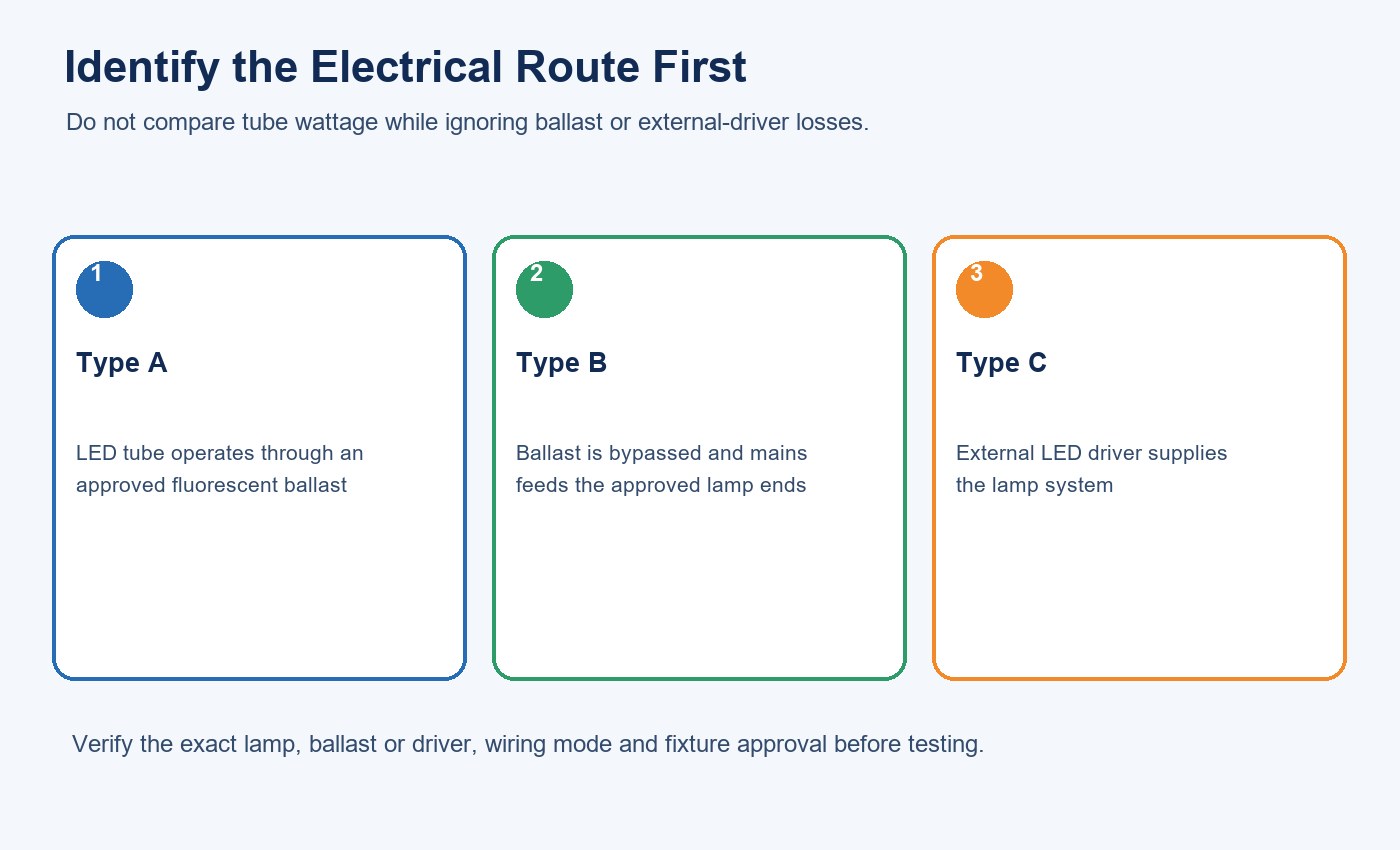
DOE FEMP guidance distinguishes three common TLED electrical architectures: Type A, Type B and Type C.
The electrical architecture changes system power, compatibility, installation work and future maintenance. Type A operates through a compatible fluorescent ballast. Type B bypasses the ballast and connects line voltage to an internal lamp driver. Type C uses an external LED driver after the fluorescent ballast is removed.
For Type A, obtain the approved lamp-ballast compatibility information and test every ballast family found on site. Include ballast losses in the power measurement. For Type B, verify single-ended or double-ended input, lampholder requirements, wiring instructions and relabelling. For Type C, treat the tube and external driver as one specified system.
The commercial LED tube selection guide covers the broader audit and route-selection process. The optical comparison should begin only after the electrical configuration and existing-fixture condition are known.
Compare Glass with Other Housing Options Fairly
A useful material comparison keeps model length, output target, color settings, electrical type and test method aligned. If one sample is clear glass and another is a heavily diffusing PC or coated tube, differences may come from both material and optical treatment.
Glass may offer dimensional stability and a familiar lamp form. Depending on construction, it can also require a breakage-control plan. Polymer or aluminium-plus-PC alternatives change weight, impact behaviour, thermal path and optical design. None of these labels proves a universal advantage.
Where breakage containment matters, the T8 Shatterproof Film Glass LED Tube illustrates a separate product architecture. Confirm the exact film, test evidence, application and cleaning protocol rather than treating every coated glass tube as equivalent.
Build a Representative Fixture Mockup
Select the difficult and common conditions from the site inventory: different reflectors, lenses, ballasts, mounting heights, orientations and control circuits. Clean one set of existing fixtures and document another in normal condition so the baseline is not distorted by unknown dirt or failed lamps.
Install the exact proposed model according to its instructions. Allow output and input power to stabilize, then record voltage, ambient condition, system watts, illuminance grid, uniformity, visual appearance, flicker behaviour and control response. Keep camera settings fixed when photographs are used to compare alternatives.
| Mockup check | Method | Acceptance record |
|---|---|---|
| Identity | Match model, housing, base, input side and label to order | Sample ID and photographs |
| Electrical | Measure system watts, current, PF and control-state input where relevant | Instrument, condition and result |
| Photometric | Grid measurements below and between luminaires; review vertical light | Baseline and proposed results at the same points |
| Visual | Inspect LED image, glare, shadows, ceiling and wall brightness | Named viewing positions and decision |
| Operational | Start, switch, dim and restore power; test emergency mode where applicable | Compatibility and exception log |
| Mechanical | Check fit, rotation, support, glass condition and fixture closure | Installation record and approved method |
The decision should name the accepted configuration and its limits. If a tube passes in an open strip light but not behind a deep prismatic lens, record two separate outcomes rather than a universal approval.
Turn the Comparison into an RFQ
Provide the existing lamp and fixture inventory, electrical route, voltage, lampholder and wiring information, controls, emergency arrangement, mounting, required illuminance, visual criteria, operating hours and destination market. Identify whether the requested housing is glass, coated glass, PC or another construction.
Request the exact model table, photometric and electrical evidence, wiring diagram, compatibility information, installation instructions, labels, sample identity and change-control process. New Lights’ factory and manufacturing capabilities page describes the route for model confirmation, sampling and production coordination.
For a defined comparison, contact New Lights with fixture photographs, the current lamp and ballast details, the required light level and the proposed operating schedule.
Frequently Asked Questions
Does a glass tube automatically transmit more light than a PC tube?
No. The result depends on the exact material, thickness, coating, haze, geometry and test method. Compare exact-model photometry and installed performance rather than the material name.
Does high transmittance guarantee high T8 LED efficacy?
No. Efficacy also depends on LED package efficiency, driver loss, thermal operation and optical distribution. Use stabilized lumens and measured input watts for the exact configuration.
Why can a high-lumen tube still produce poor lighting?
Bare-lamp lumens do not show where light goes after the tube is installed. Fixture losses, direction, glare, spacing and room geometry can reduce useful task and vertical illumination.
Should energy savings be calculated from lamp wattage?
Use installed system power. Type A projects must include ballast losses; other systems must include driver and control power. Compare equivalent operating states while confirming required light levels.
What should be approved before a production order?
Approve the exact model and housing, electrical configuration, photometric evidence, wiring, fixture mockup, visual result, labels, packaging and change-control requirements.
Editorial Sources
- New Lights, “European T8 LED Glass Tube”: https://www.new-lights.com/products/led-tube-lights/t8-led-tubes/european-t8-led-glass-tube/
- Illuminating Engineering Society, “diffuser”: https://ies.org/definitions/diffuser/
- U.S. Department of Energy FEMP, “LED Retrofit Kits, TLEDs, and Lighting Controls: An Application Guide”: https://www.energy.gov/sites/default/files/2017/03/f34/led_troffer_retrofit_guide.pdf
- U.S. Department of Energy FEMP, “Purchasing Energy-Efficient Commercial and Industrial LED Luminaires”: https://www.energy.gov/cmei/femp/purchasing-energy-efficient-commercial-and-industrial-led-luminaires