Outdoor LED wall lights fail for more than one reason. A no-light symptom may come from the supply, connection, replaceable lamp, driver, LED module, sensor or photocell. Repeated cycling may be a control or site-light problem. Water marks may originate at the rear wall interface rather than the front cover.
Reducing failure and maintenance cost therefore requires a closed process: specify the right architecture, install it correctly, record a commissioning baseline, classify symptoms, isolate the affected assembly and verify the repair. Replacing parts without identifying the cause often creates repeat service calls.
If the project is still at the selection stage, first define location, mounting and distribution with the outdoor wall and entrance lighting guide. This article begins after the application boundary is known and focuses on preventing and diagnosing repeat failures.
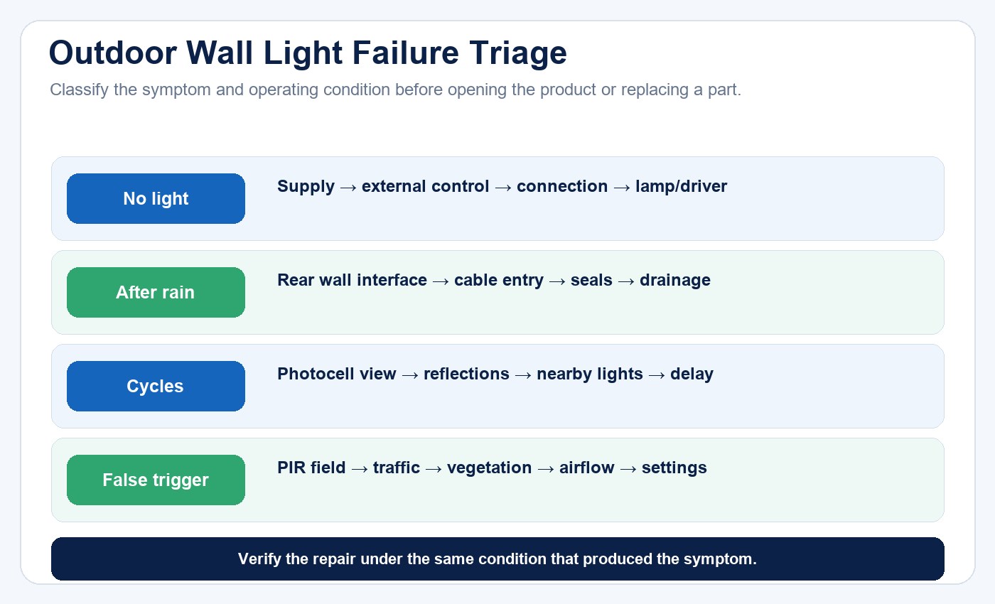
Start with the observed symptom and operating conditions, then test the most relevant failure path instead of replacing parts by guesswork.
Identify the Product Architecture First
New Lights publishes LED wall light architectures with GU10 or E27 lamp holders, integrated LED sources, PIR sensors and photocells. These versions should not share one troubleshooting assumption.
For a socket-based model, the lamp is a separate electrical and optical component. Its wattage, dimensions, voltage, dimming and thermal behavior must fit the housing. For an integrated model, the driver and LED module may be internal and may or may not be serviceable. A PIR model adds motion-detection logic; a photocell model adds ambient-light switching.
Record the complete model, suffix, lamp or driver, control option, production batch and installation date before diagnosing a fault.
| Architecture | First component boundary to isolate | Common evidence needed |
|---|---|---|
| GU10 or E27 housing | Supply, socket, replaceable lamp and enclosure | Lamp specification, socket condition and housing temperature limits |
| Integrated LED | Supply, driver, LED module and thermal path | Input behavior, driver/module identity and heat evidence |
| PIR wall light | Lighting circuit plus motion-sensing logic | Mounting height, approach direction, delay and sensitivity settings |
| Photocell wall light | Lighting circuit plus ambient-light control | Threshold, nearby light sources, reflections and switching times |
Create a Commissioning Baseline
A baseline makes later symptoms measurable. At installation, record supply voltage under approved conditions, operating power where required, switch-on behavior, light output observations, control settings and photographs of the mounting interface.
For PIR versions, document mounting height, detection area, delay and ambient-light setting. For photocell versions, record normal switch-on and switch-off conditions. Confirm that the sensor is not facing its own beam, a reflective wall, moving vegetation or frequent traffic outside the intended zone.
Inspect the rear gasket, cable entry, wall box, fasteners and drainage. An uneven surface or cable trapped across a seal can create a leak path even when the luminaire itself has an IP claim.
| Baseline item | Record at commissioning | Why it matters later |
|---|---|---|
| Product identity | Full model, option suffix, lamp or driver and batch | Prevents comparison between different electrical or control versions |
| Electrical state | Supply voltage, operating mode and approved measurements | Separates branch-circuit changes from luminaire faults |
| Mounting interface | Rear gasket, cable entry, fasteners and drainage photos | Preserves evidence of the original weather boundary |
| Control behavior | PIR or photocell settings and observed switching | Provides a reference for false triggers, missed detection or cycling |
| Optical result | Beam pattern and relevant site photographs | Shows whether later movement or obstruction changed performance |
Prevent Installation-Caused Failures
Use the approved supply, equipment class and earthing arrangement. Class I luminaires require the protective-earth connection specified by their instructions. Qualified personnel should perform branch-circuit work and electrical testing.
Match field cables, glands and wall boxes to the approved configuration. Do not drill unapproved holes or add random sealant that may block drainage, attack plastics or prevent future service. Tighten fasteners in the specified sequence and torque range where provided.
For project-level coordination across wall, path, flood and solar products, use the outdoor, garden and solar lighting solution to keep product architecture and site conditions aligned. Where a supplier must confirm mounting details, test coverage or controlled changes, include the required evidence in the RFQ and sample review; the New Lights manufacturing overview explains the available factory and project-support context.
For GU10 or E27 housings, use a lamp within the electrical, dimensional and thermal limits. An oversized or higher-power lamp can change internal temperature and prevent a cover from seating correctly.
The outdoor lighting installation checklist provides a broader site handover sequence. For a wall light, pay particular attention to the transition between the building surface and the rear of the luminaire: a perfectly intact front cover cannot compensate for a poorly sealed cable route or an uneven mounting plane.
Classify the Symptom Before Replacing Parts
Use consistent categories:
- no light;
- intermittent operation;
- flicker or unstable output;
- reduced output or color change;
- repeated on/off cycling;
- PIR missed detection or false triggering;
- photocell switches at the wrong time;
- visible moisture, staining or corrosion;
- loose, cracked or discolored parts.
Record when the symptom occurs: after rain, at a certain temperature, after warm-up, only at dusk or when another load operates. Time and environmental correlations help distinguish the luminaire from the branch circuit or control environment.
| Observed symptom | First boundary to check | Do not conclude yet |
|---|---|---|
| No light at all | Supply state, external control, connection, lamp or driver | That the LED board failed |
| Starts, then switches off | Heat, driver protection, control timing or unstable supply | That the product is underpowered |
| Cycles near dusk | Photocell view, reflections, adjacent lighting and delay | That the photocell component is defective |
| False PIR activation | Detection field, traffic, vegetation, warm airflow and settings | That the LED source is defective |
| Moisture or staining | Front, rear, cable, fastener, sensor and drainage paths | That water entered through the lens |
For a broader electrical isolation sequence, use the LED light failure diagnosis guide after the wall-interface and outdoor-control conditions have been recorded.
Diagnose No-Light and Flicker Safely
Start with safe, non-destructive checks. Confirm the correct model and external control state. Inspect for physical damage, water entry, a loose lamp, a failed external switch or a tripped protective device. De-energize and isolate the circuit according to approved procedures before opening equipment.
For a socket model, an authorized comparison with a known-compatible lamp can help isolate the lamp from the housing or supply. For an integrated model, qualified personnel may compare approved electrical measurements with the model documentation. Do not probe live mains equipment without the required training, isolation, instruments and procedure.
Flicker can involve the lamp or driver, dimmer incompatibility, supply disturbance, loose connection, control interaction or thermal protection. “Replace the driver” is not a complete diagnosis.
Investigate Water and Condensation Evidence
Water marks do not identify the entry point automatically. Inspect the front seal, rear mounting gasket, cable path, sensor interface, fastener holes, cracks and drainage. Photograph the product before disassembly and preserve the orientation.
The New Lights catalogue shows IP44 for the wall-lamp family, but an IP report must be mapped to the exact model and installed configuration. IP44 does not prove resistance to immersion, pressure washing, condensation or corrosion.
After a seal repair or part replacement, restore every gasket and interface according to the instructions. A light that operates on the bench may still be unsafe or unprotected when returned outdoors.
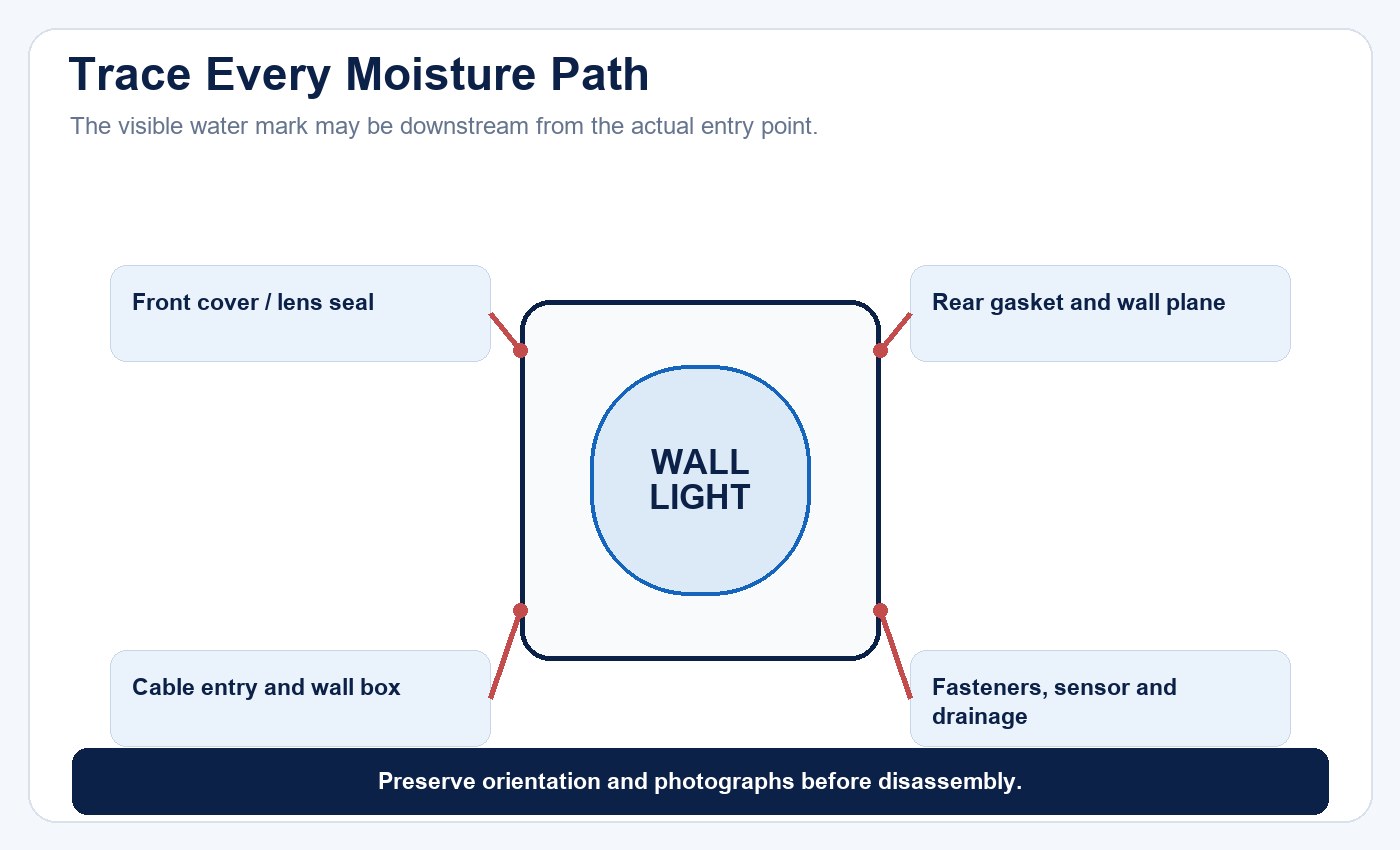
Trace moisture evidence through every interface. Water can travel behind the fitting or along a cable before it appears inside the housing.
Ingress diagnosis should distinguish a damaged product interface from an installation boundary. The tri-proof sealing and pressure testing guide explains why sealing details, deformation and the exact tested configuration matter. The same principle applies here: an IP code is meaningful only when the supplied configuration and the installed interfaces match the evidence.
| Evidence pattern | More likely path to investigate | Verification action |
|---|---|---|
| Moisture concentrated near cable entry | Gland, cable jacket, drip path or unsealed wall box | Inspect cable routing and the complete entry assembly |
| Marks behind the rear plate | Uneven wall, trapped cable or incomplete gasket contact | Remove safely, photograph contact pattern and inspect the mounting plane |
| Moisture around lens or cover | Damaged seal, debris, deformation or incorrect reassembly | Inspect mating surfaces and approved seal condition |
| Water remains after repair | Drainage blocked or the original path was not identified | Reopen the root-cause review before replacing more electrical parts |
Separate PIR Problems From Lamp Problems
PIR behavior depends on movement direction, mounting height, field of view, delay, ambient-light override and environment. Warm air outlets, vegetation, animals or traffic can produce unwanted activations. Obstructions or poor approach geometry can create missed detection.
Confirm the exact sensor settings and reproduce the symptom at the site. Check whether the light remains stable when operated in an approved override or test mode, if the model provides one. Do not assume that every unexpected switch event is a failed LED source.
A PIR wall light supports responsive illumination but is not an alarm or guaranteed security system. Maintenance records should distinguish lighting activation from security detection requirements.
Diagnose Photocell Cycling
A photocell can cycle if the luminaire’s own light reaches the sensor, if nearby lighting turns on and off, or if the threshold and delay do not suit the location. Reflections from a pale wall or canopy may contribute.
Record ambient conditions and nearby sources when cycling occurs. Verify sensor orientation, switch thresholds and hysteresis from the model documentation. Moving or covering a sensor without an approved design change can alter safety, weather protection or intended operation.
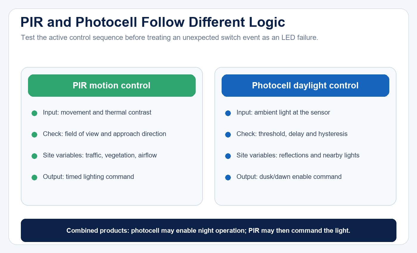
PIR and photocell faults follow different evidence paths: one responds to motion and thermal contrast, while the other responds to ambient light and switching thresholds.
When both controls are present, test their sequence rather than each component in isolation. A photocell may prevent daytime operation even when the PIR detects movement; at night, the PIR may then determine whether and how long the light remains on. Record the operating mode before interpreting the result.
Use Maintenance Records to Stop Repeats
Every service event should capture model, batch, location, exposure, symptom, operating history, photos, parts replaced and verified root cause. Retain failed components for recurring or safety-related cases.
Calculate rates with a denominator. Ten incidents across 100 installed units differ from ten across 10,000. Separate early production defects, installation issues, environmental damage, normal wear and external supply faults. Without this classification, a “failure rate” can misdirect corrective action.
Track repeat visits to the same location. A second driver replacement may indicate unresolved heat, surge, water or supply stress. Correct the system cause rather than continuing blind replacement.
The lighting maintenance and spare-parts planning guide can be used to convert service records into stocking and replacement decisions. For exposed sites, classify failures by location and weather exposure as well as by product model; otherwise a drainage or wall-construction problem may be mistaken for a batch defect.
Control Replacement Parts and Changes
Use approved lamps, drivers, sensors, seals and fasteners. A substitute may fit physically while changing current, temperature, dimming, detection or ingress protection. Record revisions and confirm whether certification or test coverage remains valid.
For serviceable seals, define when replacement is mandatory. Clean mating surfaces without damaging coatings or plastics. After reassembly, perform the approved electrical, functional and sealing checks.
A physically compatible substitute is not automatically an equivalent part. Before approval, map its electrical rating, dimensions, temperature limit, control behavior and sealing interface to the original design. If a project needs a more robust enclosed format, compare the application boundary with IP65 LED bulkhead lights rather than modifying a wall light beyond its intended configuration.
Maintenance Checklist
At planned intervals, inspect:
- Housing, lens and mounting security.
- Rear interface, glands, seals and drainage.
- Cracks, discoloration, corrosion and moisture evidence.
- Lamp seating or integrated-source operation.
- PIR detection and delay where fitted.
- Photocell switching where fitted.
- Nearby vegetation, new signs or sources affecting controls.
- Records of repeat faults by model and location.
The interval should reflect exposure, access cost, project risk and manufacturer instructions. There is no universal schedule for every wall light.
Conclusion
Outdoor wall-light reliability improves when product architecture, installation, environment and service data are managed together. Establish a baseline, classify the symptom, preserve evidence, isolate the failed assembly and verify both function and protection after repair.
For a bounded technical review, contact New Lights with the model, symptom, installation photos, supply, control settings and operating history. A complete evidence set makes it possible to separate a product issue from a wall interface, control setting, external circuit or environmental cause.
FAQ
Why does an outdoor wall light stop working after rain?
Possible causes include ingress at the front, rear wall interface, cable entry or another damaged joint. Preserve evidence and inspect the complete installation.
Why does a PIR wall light turn on unexpectedly?
Movement, vegetation, animals, traffic, warm airflow, settings or mounting geometry may contribute. Verify the exact sensor behavior before replacing the lamp.
Why does a photocell wall light cycle on and off?
Its own light, nearby sources, reflections or unsuitable threshold/delay behavior may affect it. Check the documented installation and settings.
Can a GU10 or E27 lamp be replaced with any LED bulb?
No. The base, voltage, size, power, thermal condition, beam and dimming must fit the housing and instructions.
Does IP44 prevent condensation?
No. IP44 addresses defined ingress tests and does not independently establish condensation or corrosion resistance.
How can maintenance cost be measured?
Track labor, travel, parts, repeat visits and downtime by model and root cause. Compare against installed quantity and operating period; do not claim a saving without a baseline.
Editorial Sources
- New Lights, “LED Wall Lamp”: https://www.new-lights.com/product/led-wall-lamp/led-wall-lamp.html
- New Lights, “LED Wall Lamp” catalogue: https://www.new-lights.com/new-lights/2024/12/06/ledwalllamp.pdf
- U.S. Department of Energy, “LED Systems Reliability Consortium”: https://www.energy.gov/cmei/ssl/led-systems-reliability-consortium
- International Electrotechnical Commission, “IEC 60529: Degrees of protection provided by enclosures (IP Code)”: https://webstore.iec.ch/en/publication/2452