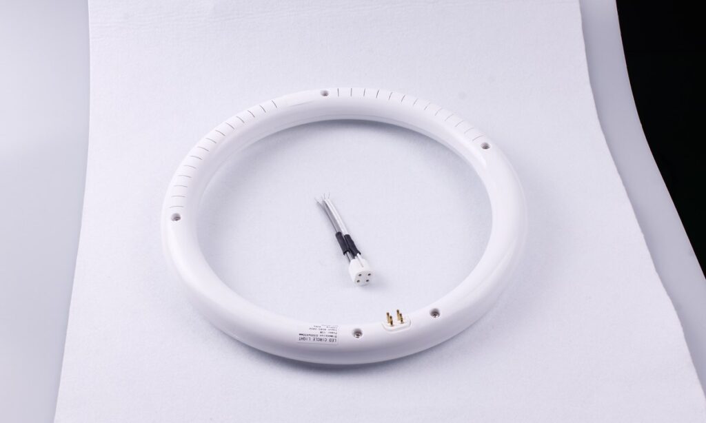
A commercial LED tube retrofit should begin with the installed fixture population, not a replacement-wattage or lamp-price comparison. Two luminaires that look identical may contain different ballasts, lampholders, wiring, emergency gear or controls. Those differences can change the permitted lamp architecture, installation work, labeling, photometric result and future maintenance route.
The practical sequence is: survey and group the existing system, compare Type A, Type B, Type A+B, Type C and complete-luminaire routes, verify the exact electrical and optical boundary, then pilot each representative configuration before rollout.
Survey the Existing Fixture Population
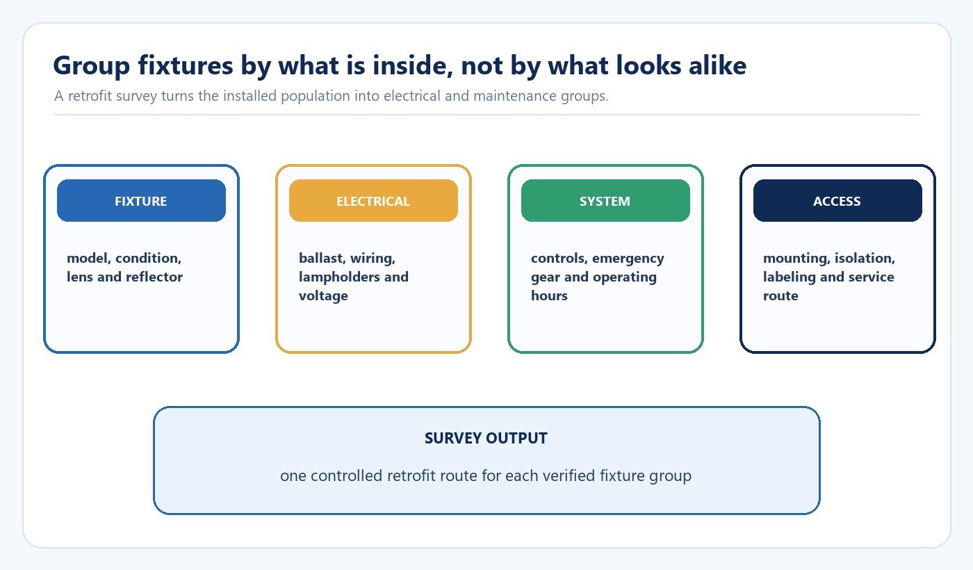
Record fixture make and model, quantity, fluorescent lamp type, ballast model, input voltage, lampholder configuration, conductor condition, emergency function, controls, mounting, lens, reflector and physical condition. Group only configurations that match in the fields that can change compatibility or field work.
| Survey field | Record | Decision it affects |
|---|---|---|
| Existing lamp and fixture | Base, length, housing, lens, reflector and condition | Mechanical fit, distribution and whether the housing should be retained |
| Ballast and wiring | Exact ballast model, input, circuit and lampholder state | Type A compatibility or Type B/C conversion scope |
| Controls and emergency equipment | Dimming, sensors, schedules and emergency function | Driver compatibility, commissioning and separate emergency verification |
| Site conditions | Temperature, moisture, dust, operating hours and access | Product construction, test conditions and labor |
Open internal electrical compartments only after isolation and by personnel qualified for the work. Photograph labels and wiring before disassembly so that the survey remains traceable to each fixture group.
Compare the Five Practical Retrofit Routes
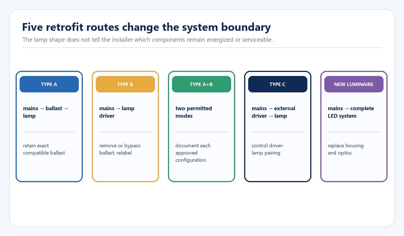
The U.S. Department of Energy distinguishes Type A, Type B and Type C tubular LED systems. Type A operates through a compatible fluorescent ballast. Type B disconnects or bypasses the ballast and supplies line voltage to the lamp circuit. Type C replaces the ballast with an external LED driver. A Type A+B hybrid supports more than one permitted mode, but each mode still needs its own approved wiring and compatibility boundary.
| Route | Component retained | Main advantage | Main boundary to verify |
|---|---|---|---|
| Type A | Compatible ballast and fixture | Least field modification | Exact ballast compatibility, ballast condition and control behavior |
| Type B | Fixture body and suitable lampholders | Removes ballast from future maintenance | Line-voltage wiring, lamp-end architecture, labels and installer scope |
| Type A+B | Depends on operating mode | Flexible transition strategy | Both approved modes and clear future identification |
| Type C | Fixture body plus new external driver | Central driver and control options | Driver-lamp pairing, wiring and service access |
| New luminaire | Usually branch circuit only | New optics, housing and controls | Mounting, photometry, controls, disposal and project cost |
The U.S. General Services Administration 2024 guidance records that its 2024 P100 did not allow Type B TLEDs because of compatibility and safety concerns. That is a U.S. federal-building requirement, not a universal prohibition. Apply the current rules and contract documents for the project jurisdiction.
Define the Electrical and Installation Boundary
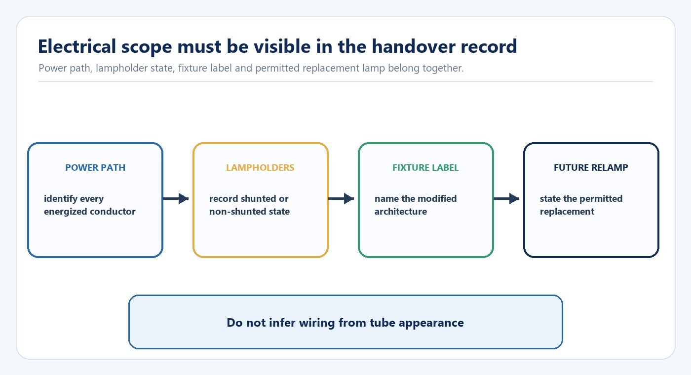
For Type A, require an exact lamp-ballast compatibility list and test representative installed units. Ballasts of different models or ages can behave differently with the same lamp. The retained ballast also remains a service component and a source of system losses.
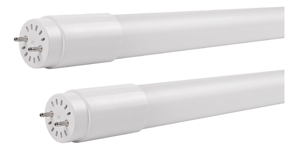
For Type B, document whether supply is single-ended or double-ended, whether lampholders must be non-shunted, which conductors are removed or retained, and what fixture labels are required. Never infer the power arrangement from the cap or tube appearance. The single-ended versus double-ended power guide extends this wiring decision.
For Type C, preserve the external driver identity, output range, connector, lamp pairing and replacement route. The TLED driver selection guide explains why a driver cannot be selected from wattage alone.
The International Electrotechnical Commission’s IEC 60598-1:2024 specifies general safety requirements and tests for luminaires. The applicable lamp, retrofit kit, modified luminaire and destination market determine the exact conformity route; a general standard reference does not replace model- and project-specific evaluation.
Check Photometry, Controls and Emergency Functions
Bare-lamp lumens do not predict the complete installed result. Existing reflectors, louvers and lenses can change distribution, glare, vertical light and efficiency. Compare the current and proposed systems under the same measurement plan: task-plane and vertical illuminance, uniformity, visible source brightness, color appearance and flicker where relevant.
Controls add another system boundary. Operate occupancy sensors, daylight controls, schedules and dimmers through their real sequences, including minimum level, fade behavior and loss-of-communication state. Emergency luminaires require separate verification of charging, changeover, lamp or driver compatibility and the project-required duration.
| Function | Pilot observation | Acceptance record |
|---|---|---|
| Lighting result | Illuminance at agreed points, distribution, glare and color | Before-and-after measurements with fixture identity |
| Electrical behavior | Input power, start, noise, abnormal heat and switching | Instrument, condition and pass criteria |
| Controls | Detection, dimming range, schedules and failure behavior | Device models, settings and commissioning record |
| Emergency operation | Changeover, output and required duration | Exact emergency equipment and test result |
The LED tube versus fluorescent guide covers the wider system comparison, while the sample evaluation checklist provides a consistent record for competing samples.
Run a Representative, Labeled Pilot
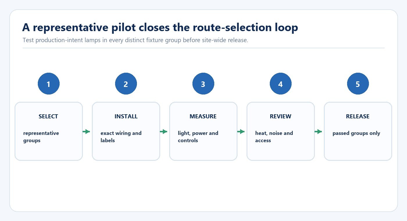
Select difficult and typical fixtures rather than only the easiest location. Include different ballast groups, older lampholders, emergency equipment, controls, enclosed housings and unusual access where they exist. Install the production-intent lamp and required components, then record the final wiring and label arrangement.
Measure the existing and proposed systems under the same conditions. Review light levels between fixtures, glare, color, flicker, start-up, control behavior, noise and abnormal heat. Record installation time, access constraints, removed-component handling and the future replacement instruction.
Release only groups that meet the documented acceptance criteria. A group that fails may need a different lamp architecture, a retrofit kit or complete luminaire replacement rather than an undocumented field variation.
Plan Maintenance and Change Control
The retrofit is incomplete if a future technician cannot identify the permitted replacement. Keep the approved lamp, ballast or external driver, wiring diagram, fixture label, control settings and emergency boundary in the asset record. Separate visually similar Type A and Type B lamps in storage and documentation.
A product substitution should trigger an impact review when it changes the driver, LED board, housing, diffuser, wiring, cap, control interface or other part that can affect electrical, thermal, optical or safety performance. The factory audit checklist helps assess how approved parts and production changes are controlled.
Commercial Retrofit Release Checklist
Before rollout, confirm:
- Every fixture population is grouped by actual ballast, wiring, lampholders and system function.
- The selected Type A, B, A+B, C or new-luminaire route is named for every group.
- Compatibility evidence matches the exact lamp, ballast, driver and control devices.
- Wiring diagrams, lampholder requirements, labels and installer responsibility are documented.
- Photometry, glare, color and flicker are checked in representative spaces.
- Controls and emergency circuits are validated separately.
- Pilot records include photos, wiring, measurements, settings and deviations.
- Maintenance instructions prevent an incompatible future replacement.
- Product and component revisions are tied to the approved sample.
- Exceptions are routed to a separate engineering decision before rollout.
For project-specific review, continue with the fluorescent replacement solution or contact New Lights with the fixture survey, destination market, required controls, quantity and approval documents.
Frequently Asked Questions
Can one Type A LED tube work with every fluorescent ballast?
No. Compatibility must match the exact lamp and ballast combination, including the relevant operating conditions and controls.
Can a Type B LED tube be installed like an ordinary replacement lamp?
No. Type B changes the fixture electrical architecture and requires the correct wiring, lampholders, labels and qualified installation for the product and market.
When should a project replace the complete luminaire?
Include a new luminaire when the existing housing, wiring, optics, controls or maintenance condition makes lamp-level retrofit risky, inefficient or difficult to support.
Editorial Sources
- U.S. Department of Energy, “Upgrading Linear Fluorescent Fixtures to LED in Schools”: https://www.energy.gov/sites/default/files/2024-12/upgrading-led-schools_nov24.pdf
- U.S. General Services Administration, “LED Lighting and Controls Guidance”: https://www.gsa.gov/governmentwide-initiatives/federal-highperformance-buildings/highperformance-building-clearinghouse/emerging-technology-evaluations/lighting/led-and-controls-guidance
- IEC, “IEC 60598-1:2024 — Luminaires — Part 1: General requirements and tests”: https://webstore.iec.ch/en/publication/66620