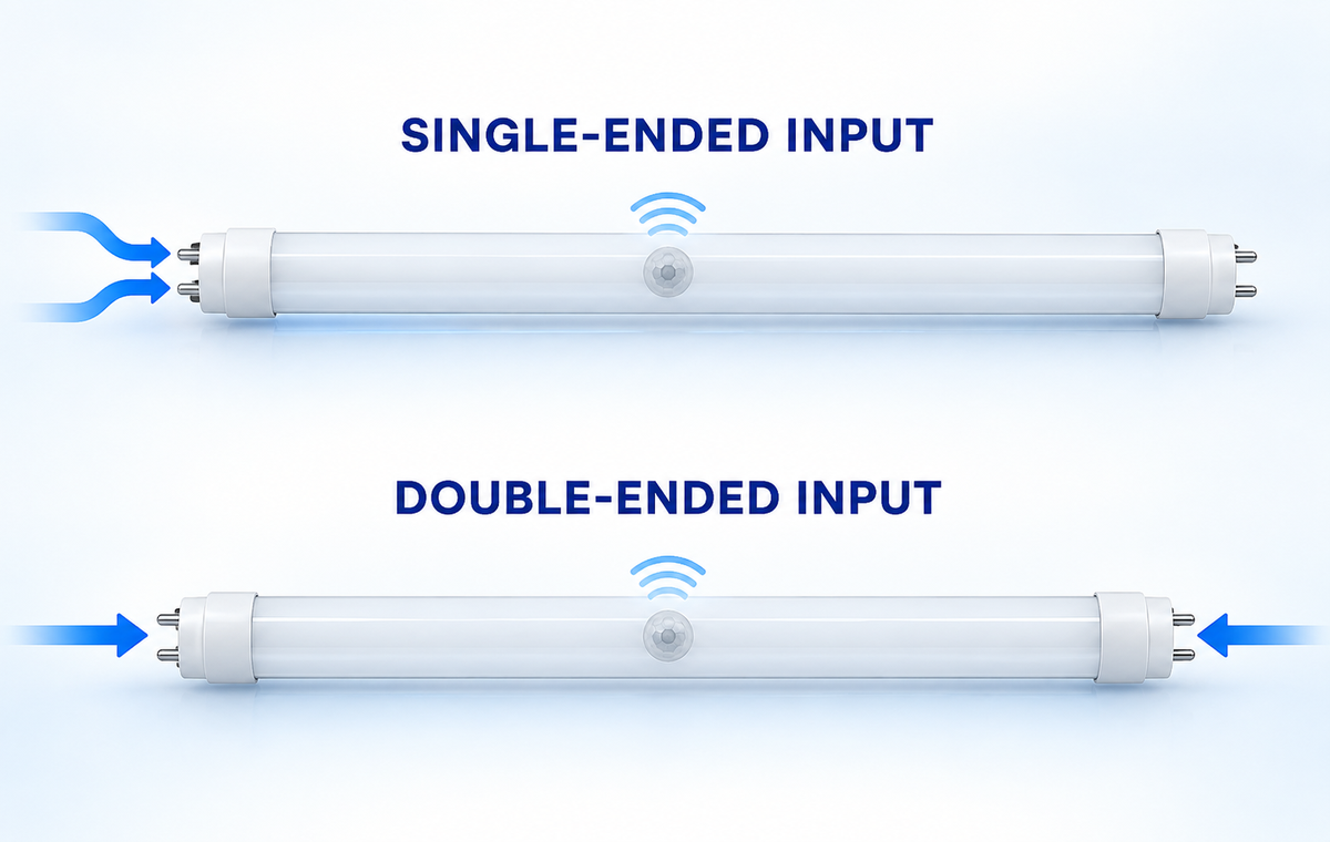
Single-ended and double-ended describe where an exact T8 LED tube expects its electrical input. A single-ended lamp receives the required input at one end; a double-ended lamp uses opposite ends. Neither term identifies the pin map, lampholder construction, ballast path or microwave-sensor behavior for an unknown model.
The practical rule is simple: identify the lamp, fixture and approved installation document before changing the fixture. If any of those three is missing or inconsistent, the project is not ready for wiring. This is especially important for a sensor tube because the sensing circuit may need a defined supply state while the LED output is off, reduced or waiting for motion.
This guide helps contractors and facility teams choose the correct decision path. Exact conductor placement remains in the instructions for the approved lamp and retrofit system. For the wider retrofit taxonomy, start with the LED tube installation guide; the sections below focus on input location and sensor commissioning.
Separate the Three Decisions That Are Often Confused
Three labels can appear in the same project, but they answer different questions:
- Retrofit architecture asks whether the lamp operates on an existing fluorescent ballast, from the branch circuit through fluorescent-style lampholders, or with an external LED driver.
- Input location asks whether the exact lamp receives its specified input at one end or across opposite ends.
- Sensor architecture asks how the microwave sensor, control electronics and LED driver receive power and how they command light output.
UL Solutions describes Type A lamps as direct fluorescent replacements operating on a compatible host ballast and Type B lamps as products intended for fluorescent-style lampholders wired to the branch circuit. Type C systems use an external LED driver. These Type A/B/C categories do not, by themselves, reveal which contacts an individual lamp uses.
A tube can therefore be described as Type B and still require a separate single-ended or double-ended determination. Likewise, “microwave sensor” identifies a control function, not a universal input arrangement. Treating any one label as a complete wiring answer is the core error this workflow prevents.
Compare What the Two Input Arrangements Actually Change
The two arrangements alter fixture preparation, lampholder requirements, relamping controls and the evidence needed for approval. They do not create a universal winner.
| Decision point | Single-ended input | Double-ended input | What must control the decision |
|---|---|---|---|
| Input location | Required input is at one marked end | Required input is distributed across opposite ends | Exact lamp marking and installation document |
| Lampholders | The powered end may require a specified contact arrangement | Each end must match the manufacturer’s contact arrangement | Approved socket type, condition and internal connections |
| Lamp orientation | The marked input end may have a required fixture position | Some models may allow either orientation; others may not | Model instructions rather than appearance |
| Fixture conversion | May require changing one or both lampholders and applying labels | May retain or replace lampholders under the approved kit | Certified conversion scope and host fixture criteria |
| Future relamping | A visually similar lamp with another pin map may be hazardous | A single-ended replacement may be incompatible with the converted fixture | Durable fixture label and controlled replacement list |
| Sensor operation | Internal sensor supply and switching remain model-specific | Internal sensor supply and switching remain model-specific | Sensor data, approved diagram and commissioning record |
Single-ended input can concentrate the supply interface at one end, while the exact pin functions and acceptable shunted or non-shunted lampholder remain defined by the product instructions. Double-ended input can distribute the supply across the lamp, while the same instructions still control which pins are used and whether lamp orientation is interchangeable.
Manufacturer documentation shows why the distinction must remain model-specific. For example, LEDVANCE publishes installation instructions that separately depict single-ended and double-ended Type B configurations for products covered by that document. Those drawings support the broader lesson that products sharing the T8 form factor can require different approved arrangements; they are not instructions for another manufacturer’s lamp.
Understand Why the Microwave Sensor Changes the System
A non-sensor lamp can be controlled simply by applying or removing power. A microwave-sensor tube may need its sensing and control electronics energized while the LED output waits, dims or switches. The required supply state depends on the internal driver and control topology.
That distinction creates several second-order questions:
- Will an upstream wall switch or occupancy controller remove the power the internal sensor needs?
- Does the lamp switch only its LED load, or does it coordinate with other lamps or a separate control device?
- What happens after a power interruption or during the sensor’s initialization period?
- Can metal reflectors, wireways or fixture covers alter the intended detection pattern?
- Will movement in an adjacent aisle, behind a partition or outside the intended zone create false triggers?
- Are hold time, sensitivity, daylight threshold and standby level fixed or adjustable for the exact model?
Microwave sensing uses radio-frequency energy and can respond differently from passive infrared sensing. Fixture construction, mounting height, orientation, moving machinery and adjacent traffic can all change the observed detection zone. A catalog range is therefore a starting point for layout, not a substitute for commissioning in the installed environment.
The sensor review also needs the target market. Frequency authorization, electromagnetic compatibility and safety documentation are product- and market-specific. Do not infer those approvals from a generic sensor description or from a visually similar tube.
Build an Evidence Pack Before Opening the Fixture
The most efficient retrofit starts with a complete record, not with removing the ballast cover. Photograph and record the equipment while the fixture is safely deenergized:
- lamp manufacturer, model, markings and both end caps;
- fixture manufacturer, model, supply and field-modification labels;
- ballast or external driver manufacturer and model, if present;
- lampholder type, condition and any visible internal connections;
- number of lamps and the existing control arrangement;
- emergency, dimming, relay or building-control components;
- mounting height, reflector, lens, enclosure and sensor orientation;
- target detection zone, unwanted detection areas and operating schedule;
- destination market and the required safety and RF/EMC documents;
- the exact installation instructions supplied for the proposed lamp or conversion kit.
Compare the equipment markings with the document revision and covered models. A drawing for another length, input version or product family is not an acceptable substitute. If the fixture was previously converted, preserve its field label and determine what replacement family the conversion permits.
For projects spanning many fixtures, the commercial LED tube retrofit guide helps turn the survey into a controlled rollout. The fluorescent lighting replacement solution places this lamp-level decision within the wider choice between relamping, conversion kits and complete luminaires.
Use a Stop-or-Proceed Decision Matrix
The evidence pack should lead to an explicit decision. “The tube fits” is not an approval state.
| Finding | Decision | Why |
|---|---|---|
| Exact lamp and approved instructions match the fixture and market | Proceed to qualified installation planning | Input location, socket requirements and conversion scope are defined |
| Lamp is identified but the diagram or certification scope is missing | Stop and obtain the controlled document | The pin layout and field modification cannot be inferred safely |
| Fixture label conflicts with the proposed lamp instructions | Stop and resolve the conflict with the responsible manufacturer or authority | The host fixture may have been modified or may fall outside the kit scope |
| Ballast remains but no exact compatibility is published | Do not treat it as a Type A replacement | Mechanical fit does not establish ballast compatibility or sensor operation |
| Sensor data is available but electrical input is not | Stop; sensor settings cannot replace an electrical installation document | Detection behavior and supply architecture are separate evidence chains |
| Electrical installation is defined but the detection zone is unsuitable | Reposition, reselect or redesign within approved limits | A safe electrical conversion can still fail the operational task |
| Emergency equipment or another controller is present | Escalate to a system-level review | The tube may interact with life-safety or control functions outside a simple relamp |
This matrix lets a buyer or facility manager make an independent project decision without attempting electrical work: proceed only when the exact identities and documents agree; otherwise stop and close the missing evidence.
Keep Electrical Work Within a Qualified, Deenergized Process
Fixture conversion can expose line-voltage parts. OSHA’s interpretation of 29 CFR 1910.333 states that a qualified person must use test equipment to verify that the circuit elements and electrical parts to which employees will be exposed are deenergized. A wall switch or indicator is not sufficient verification.
The work plan should identify all energy sources, apply the site’s lockout or tagging procedure, verify the deenergized condition, follow the approved conversion instructions, preserve grounding and enclosure integrity, and apply every required field label. Reenergization follows only after tools, temporary devices and exposed work have been cleared and the fixture is closed.
This safety boundary matters because a trial-and-error approach can energize unintended contacts, damage electronics or leave a converted fixture unsafe for future relamping. Swapping ends, adding a jumper or moving conductors to “see if it works” is not a diagnostic method.
Commission the Light and Sensor as Two Linked Functions
Installation completion is not the same as operational acceptance. Commission the fixture from normal approach paths and under representative ambient-light conditions.

First verify normal lighting behavior: stable start, expected output, no abnormal flicker or noise, correct operation after power interruption, and consistent behavior across all lamps in the fixture. Then verify sensor behavior: intended entry paths, missed-detection areas, false triggers, hold time, daylight threshold, standby state and interaction with adjacent sensors.
Repeat multiple cycles. One successful trigger directly under the fixture does not establish the detection boundary. Test movement beyond the target zone, nearby doors, fans, vehicles or machinery, and any partition through which microwave energy may propagate.
Record the lamp model, input arrangement, fixture identity, conversion label, sensor settings, test positions, results and approver. The LED lighting sample evaluation checklist provides a reusable structure when several lamp or setting candidates must be compared.
Diagnose Problems Without Guessing at the Wiring
Use symptoms to choose the next evidence check, not to improvise energized changes.
- No light and no apparent sensor response: verify the documented supply path, circuit state and model match through the qualified work process.
- Light operates but does not respond as expected: check initialization time, daylight threshold, sensitivity, hold time, override mode and the documented sensor state.
- Light remains on: look for continuing detection, adjacent movement, hold-time settings, daylight logic or an override before treating the problem as an electrical fault.
- False triggers: review orientation, metalwork, doors, fans, vehicles, neighboring aisles and overlapping sensors.
- Missed detection: compare mounting height, target movement direction, obstructions and sensitivity with the model’s commissioning instructions.
- Different lamps behave differently: confirm model, production configuration, settings and fixture control before assuming a batch defect.
If the observed behavior conflicts with the approved document, isolate the fixture and escalate the discrepancy. A generic online diagram should never overrule the product marking or controlled installation information.
Preserve the Configuration for Future Relamping
A converted fixture can accept a lamp that fits mechanically but is electrically incompatible. Prevent that maintenance error by keeping durable conversion labels visible and maintaining a controlled replacement record.
The handover pack should include the installed lamp model, input arrangement, approved instructions, fixture and conversion-kit identities, lampholder requirements, sensor settings, commissioning results, photographs and approved alternatives. Train maintenance staff to compare the replacement against this record rather than relying on tube length or pin appearance.
Update the record after any lamp, driver, ballast, lampholder, sensor or control change. Recommission the detection zone when the fixture position, surrounding racks or operating pattern changes.
Frequently Asked Questions
Is every microwave-sensor T8 tube single-ended?
No. Input location is model-specific. Use the exact lamp marking and approved installation document to identify whether the product is single-ended or double-ended.
Does a Type B label tell me which pins receive power?
No. Type B identifies a branch-circuit retrofit architecture; the individual product instructions define the input location, contacts, lampholders and conversion details.
Can I identify the arrangement from a shunted or non-shunted socket?
The socket is one item to inspect, but appearance alone cannot establish its complete internal connection or the lamp’s required pin map. Verify both against the approved instructions.
Why can a microwave-sensor tube misbehave even when it lights?
The LEDs and sensor have linked but distinct operating requirements. Upstream controls, initialization, daylight settings, hold time, fixture metalwork and movement outside the intended zone can affect sensor behavior.
What should I send for a model-specific review?
Send clear photographs of both tube ends and all markings, the fixture and ballast or driver labels, lampholders, existing wiring record, supply market, controls, mounting environment and required sensor behavior. Contact New Lights with that evidence before approving a configuration.
Editorial Sources
- UL Solutions, UL Certified LED Retrofit Luminaire Conversion Kit FAQs: https://code-authorities.ul.com/about/blog/led-retrofit-kits-ul-certified-luminaire-retrofit-kit-faqs/
- UL Solutions, New Edition and Scope Expansion of the LED Retrofit Standard: https://www.ul.com/news/new-edition-and-scope-expansion-led-retrofit-standard
- Occupational Safety and Health Administration, Verification of Isolation and Deenergization: https://www.osha.gov/laws-regs/standardinterpretations/2012-12-12
- Occupational Safety and Health Administration, Electrical Safety-Related Work Practices: https://www.osha.gov/enforcement/directives/std-01-16-007
- LEDVANCE, DUALescent LED T8 Type B Installation Guide: https://assets3.ledvanceus.com/media/resource/original/asset-13222335