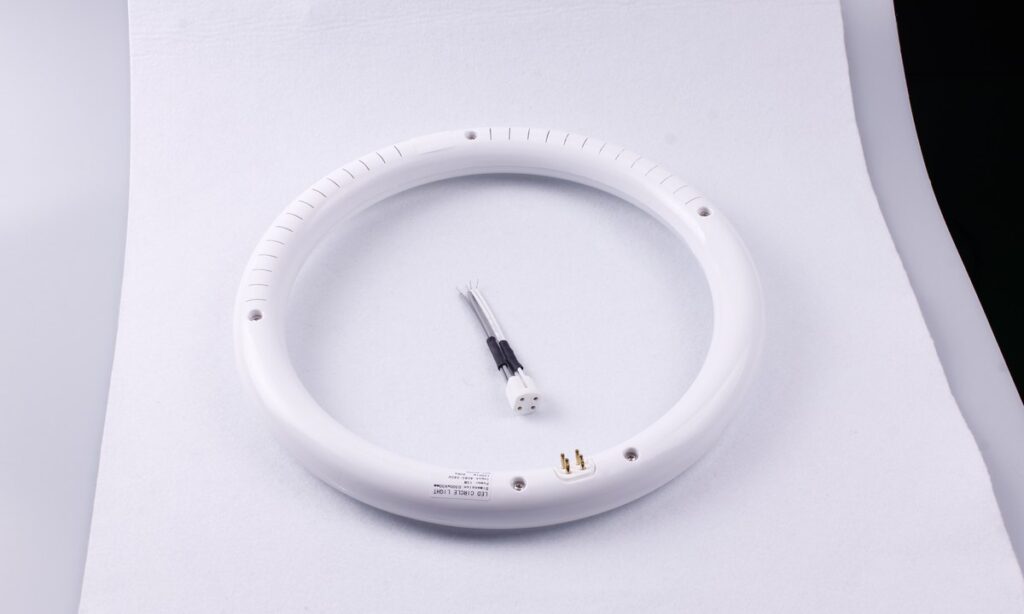
The first step in an LED tube installation is not removing the ballast or connecting a wire. It is identifying the exact lamp type and the certified installation method printed in its documentation.
Tubular LED lamps can look similar while using different power arrangements. A Type A lamp operates through a compatible fluorescent ballast. A Type B lamp is used after a defined ballast-bypass conversion. A Type A+B lamp supports more than one mode under specific instructions. A Type C system uses an external LED driver. Mixing those methods can create shock, fire, equipment and future-maintenance risks. If the retrofit route has not been selected, first compare the systems in the LED tube versus fluorescent tube guide.
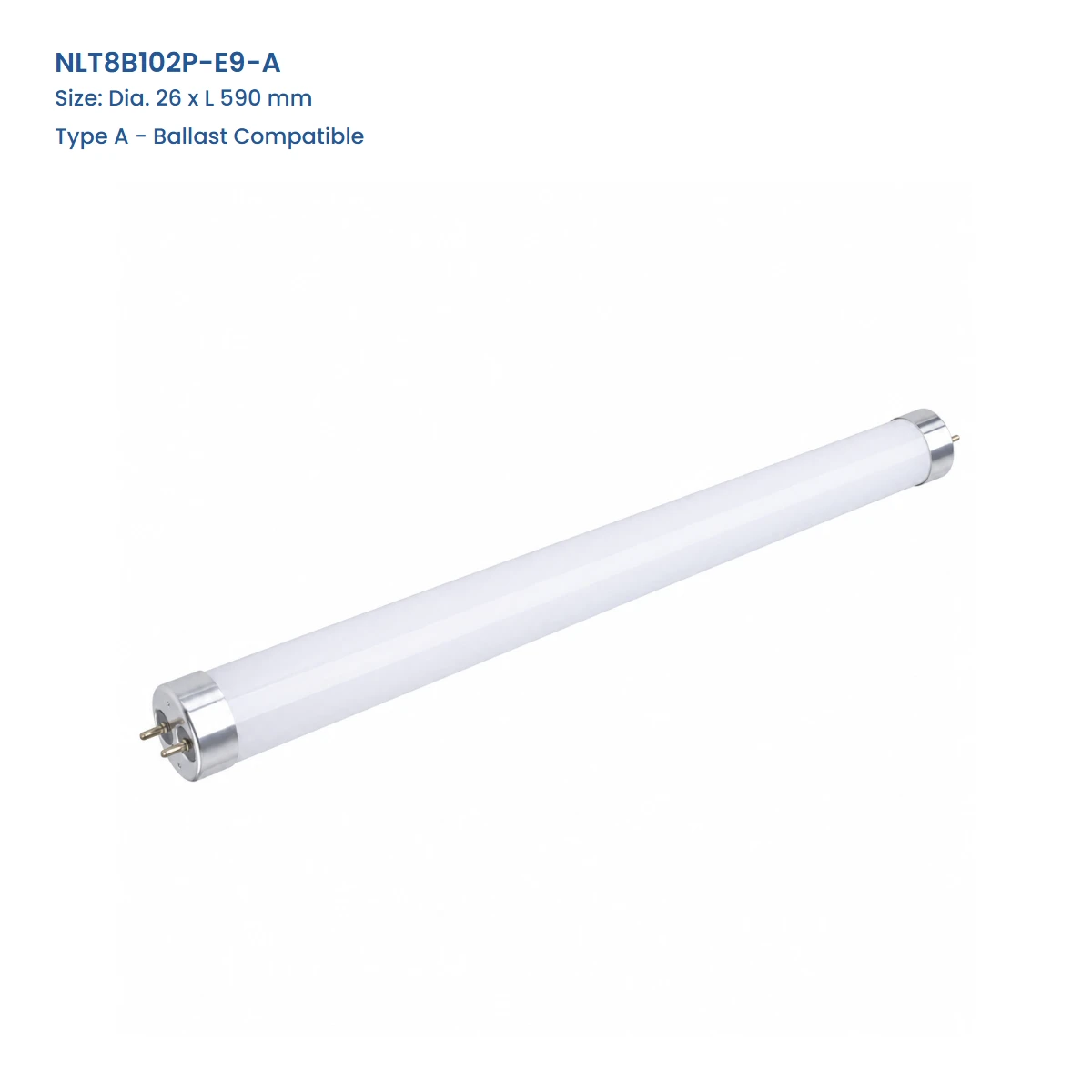
Terminal wiring comes from the certified instructions for the exact lamp or retrofit kit. Line-voltage conversion should be performed by qualified personnel under the rules that apply to the project.
Stop Until These Items Are Identified
| Tube type | Existing ballast | Power arrangement | Approval evidence to verify |
|---|---|---|---|
| Type A | Remains in service | Through a listed compatible ballast | Exact lamp-ballast compatibility documentation |
| Type B | Disconnected or removed | Line voltage under the certified retrofit instructions | Wiring mode, lampholder requirements, labels and conversion instructions |
| Type A+B | Depends on the selected operating mode | Ballast-compatible or defined direct-wire mode | Approval and instructions for the mode actually used |
| Type C | Replaced by an external LED driver | Driver output supplied to compatible tubes | Exact driver-lamp pairing, controls and installation layout |
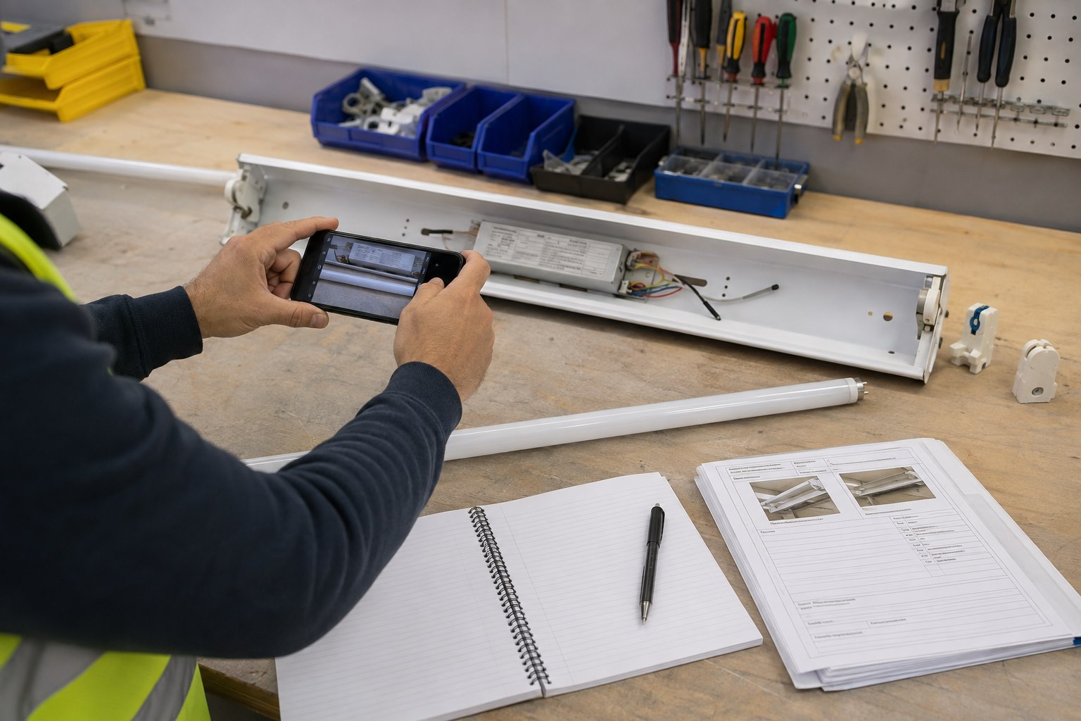
Photograph and record the following before ordering or installing a tube:
- Existing fluorescent lamp designation, length, base and quantity.
- Ballast manufacturer, model, voltage and wiring label.
- Fixture label and luminaire construction.
- Lampholder type and condition.
- Branch-circuit voltage.
- Emergency ballast, battery, sensor or dimming equipment.
- Proposed LED tube model and every marking on the lamp and package.
- Approved installation instructions and retrofit labels supplied with that model.
Do not infer the installation method from “T8,” “G13,” tube length or connector appearance alone.
Build the Installation Submittal
Before work begins, place the product and site evidence in one controlled submittal. It should identify the exact LED tube, its approved operating mode, the host fixture, compatible ballast where applicable, branch voltage, lampholder requirements, emergency or control equipment and the instructions that will be issued to installers.
Include the proposed retrofit labels and show where they will remain visible after the fixture is closed. If a project contains more than one ballast or fixture type, create a separate line in the schedule for each combination. A single approval for “T8 fixtures” is too broad when the site contains different wiring, ballasts or emergency arrangements.
The submittal becomes the handoff between purchasing, engineering, the installer and future maintenance. Revise it when a lamp, driver, ballast or operating mode changes; a substitution should not inherit the approval of the original combination without review.
Type A: Ballast-Compatible Replacement
A Type A TLED is designed to operate through specified fluorescent ballasts. The fluorescent ballast remains connected, and the lamp’s internal electronics receive power through that system.
The process appears similar to a lamp replacement, but compatibility remains the central requirement:
- Confirm that the exact ballast appears on the current compatibility documentation for the exact LED tube.
- Confirm voltage, lamp quantity and emergency/control conditions.
- De-energize and verify the circuit under the applicable safety procedure.
- Inspect lampholders, wiring and the host fixture for damage.
- Install the tube in the orientation required by its instructions.
- Reassemble the fixture and commission a representative sample.
If the ballast is missing from the compatibility list, do not treat a successful momentary start as approval. Flicker, unstable operation, reduced output or later failure can appear even when a lamp initially lights.
Type A also retains the ballast as an energy-using and maintainable component. Record what happens when that ballast reaches end of life: replace it with another compatible ballast, convert under an approved A+B route, or adopt another retrofit system.
Type B: Ballast-Bypass Conversion
A Type B tube operates from line voltage after the fluorescent ballast is disconnected or removed according to the certified retrofit instructions. The host luminaire is being converted, not merely relamped.
Important details vary by model:
- Whether power is supplied at one end or both ends.
- Which pins or lampholders are energized.
- Whether existing lampholders are permitted or must be replaced.
- What internal conductors are removed, terminated or reconfigured.
- Which retrofit and replacement-warning labels must be applied.
- Whether a disconnect or other component is required.
Use the instructions packaged with the exact certified lamp or kit. A diagram copied from another tube can energize the wrong pins or leave an unsafe future lamp-replacement condition.
UL Solutions has warned about specific lamps authorized for Type A use being marked or installed for unapproved line-voltage operation. The broader lesson is simple: certification for one operating mode does not authorize another.
Type A+B: Confirm Which Approval Applies
Dual-mode lamps can operate through a compatible ballast and can also support a specified direct-wire mode. That flexibility does not make every conversion automatic.
UL Solutions explains that an A/B lamp used for luminaire conversion needs the applicable retrofit-kit evaluation and marking, not only a stand-alone lamp listing. Confirm both the present mode and the future maintenance plan:
- Is the existing ballast on the approved list?
- Is line-voltage conversion covered by the lamp or kit certification?
- Which instructions and labels apply to the converted fixture?
- How will maintenance personnel identify the permitted replacement later?
Do not leave a converted fixture in a state where an incompatible fluorescent or LED lamp can be installed without warning.
Type C: External LED Driver System
Type C uses a separate LED driver connected to compatible tubes. The fluorescent ballast is no longer the operating gear.
The external driver, lamps, lampholders and wiring form one system. Verify the exact driver-lamp pairing, number of lamps, output wiring, controls, enclosure location, service access and thermal limits. Do not substitute an LED driver based only on nominal voltage or connector fit.
Single-Ended and Double-Ended Power
“Single-ended” and “double-ended” describe where a direct-wire tube receives power, but the words are not a complete installation specification.
For a single-ended design, the required conductors are supplied at one end according to the model instructions. For a double-ended design, the supply arrangement spans opposite ends according to that product’s design. Pin functions and lampholder requirements still need to be verified.
Never use continuity, appearance or a diagram from a different brand as the sole basis for wiring. The lamp marking, certified instructions and kit components control the installation.
Electrical Safety and Fixture Conversion
In US workplaces where OSHA 1910.333 applies, exposed live parts generally must be de-energized before work, and appropriate safety practices are required. Other jurisdictions have their own electrical rules.
For any retrofit:
- Follow the site’s isolation and lockout/tagout procedure.
- Have a qualified person verify absence of voltage with appropriate test equipment.
- Treat conductors as energized until the required verification is complete.
- Use the specified components, conductor preparation and enclosure methods.
- Apply every required conversion and replacement label.
- Close the fixture before initial energization.
If the existing fixture is damaged, contaminated, incorrectly wired or unsuitable for the proposed conversion, stop and assess repair or complete replacement.
Emergency, Dimming and Sensor Systems
Emergency and control compatibility require their own checks. Identify emergency ballasts, battery packs, dimming ballasts, occupancy sensors and building-control interfaces before selecting the tube.
Verify the approved operating mode, emergency output, transfer behavior, control range and certification for the complete proposed system. A lamp that lights on normal power may still fail the emergency or dimming requirement.
Test the most demanding operating states during the pilot. For dimming, check start level, minimum stable level, smoothness and switch-off behavior. For occupancy sensors, observe repeated switching and any programmed delay. For emergency lighting, check transfer and required output under the applicable commissioning procedure. Document which equipment was present during the test so the result is not applied to a different system later.
Where the existing controls or emergency gear cannot be matched to an approved tube solution, compare an external-driver system or complete luminaire replacement. Preserving every legacy component is not always the lowest-risk route.
Plan for Future Relamping
A converted fixture must remain understandable after the original installer leaves. Record the retrofit type, lamp model, powered-end arrangement where applicable, conversion date and replacement restrictions. Keep the certified instructions with the facility records and make sure the fixture labels can be read without dismantling unrelated equipment.
Control replacement stock. A future lamp that fits the lampholders may use a different electrical arrangement. Purchasing and maintenance teams should order against the approved model or an evaluated replacement rather than a generic length and base description.
If the approved lamp becomes unavailable, review the substitute as a new system decision. Check the existing wiring, labels, lampholders, voltage, emergency equipment and controls again before installation.
Commissioning Checklist
After installation and before broad rollout, verify a representative sample:
- Correct lamp orientation and secure seating.
- Stable start and operation at the project voltage.
- No flicker, cycling, abnormal noise or odor.
- Correct switching, dimming, sensing and emergency behavior.
- Expected light output and distribution through the existing optics.
- No unexpected exposed energized contacts during permitted maintenance actions.
- Required retrofit labels visible and legible.
- As-built records updated with lamp, mode, date and installer.
Keep the instructions and compatibility evidence with the facility records so future replacement does not reverse or confuse the conversion.
Frequently Asked Questions
Can I install an LED tube without removing the ballast?
Only when the exact tube is approved for Type A operation with the exact existing ballast and system conditions.
Does every Type B tube use the same wiring?
No. Powered end, pin arrangement, lampholder requirements and conversion steps vary by product.
Can I use a Type A+B tube as Type B later?
Only when its certified conversion instructions cover that mode and the fixture is converted and labeled accordingly.
Are shunted lampholders always acceptable?
Do not apply one answer to every tube. Use the exact product instructions, because supply design and lampholder requirements vary.
Can the old emergency ballast stay connected?
Only if the proposed system is specifically approved and tested for that emergency arrangement. Do not assume compatibility.
Is this a DIY lamp replacement?
A verified Type A relamp may be a lamp-maintenance task under applicable rules. Ballast bypass or other fixture conversion involves electrical work and should be handled by qualified personnel.
Submit the Existing-System Evidence
Start with the LED tube product families, compare the main options in the LED tube versus fluorescent tube guide, and provide the ballast label, fixture label, lampholder photos, circuit voltage, emergency/control equipment and preferred retrofit route through the New Lights contact page. Compatibility and installation instructions must be tied to the exact quoted tube before work begins.