Flexible LED filament design can reduce glare in some viewing conditions, but the word “flexible” is not a glare rating. Curving a filament changes the position, orientation and overlap of bright emitting segments. Whether that improves visual comfort depends on the resulting luminance pattern, the bulb envelope, lumen output, fixture, observer position and background.
The practical decision is therefore not “flexible or rigid?” It is “which complete bulb-and-fixture combination keeps high-luminance areas out of normal sightlines while still delivering the required light?” Compare exact models at matched output, observe them in the intended fixture and treat glare, flicker and decorative appearance as separate acceptance criteria.
Begin with the Variables That Control the Result
Glare occurs when luminances in the visual field are high enough relative to the observer’s adaptation level to cause discomfort, annoyance or reduced visual performance. The Illuminating Engineering Society notes that source size, position, luminance, number of sources and adaptation luminance all affect the sensation.
That definition immediately shows why filament shape alone cannot determine the outcome.
| Variable | What it changes | What a buyer should compare |
|---|---|---|
| Local filament luminance | How intense each visible segment appears | Calibrated luminance image or controlled side-by-side sample |
| Apparent emitting area | Whether light appears concentrated or spread over a larger area | Envelope and filament pattern from normal viewing angles |
| Position in the field of view | Direct sight of a bright source is usually more critical than a shielded view | Seated, standing and circulation sightlines |
| Number and overlap of bright segments | Several lines can merge into one visually intense region | Front, side and diagonal views |
| Background luminance | A bright source has more contrast against a dark background | Day, evening and dim-scene conditions |
| Shade, globe or reflector | Blocks, diffuses or redirects direct views | The complete fixture, not a bare bulb alone |
| Output and dimming level | Changes source luminance and useful illuminance | Matched lumens, dimmer and operating level |
If two candidates differ in several of these variables, a comfort difference cannot be credited to filament flexibility alone.
What Flexible Geometry Actually Changes
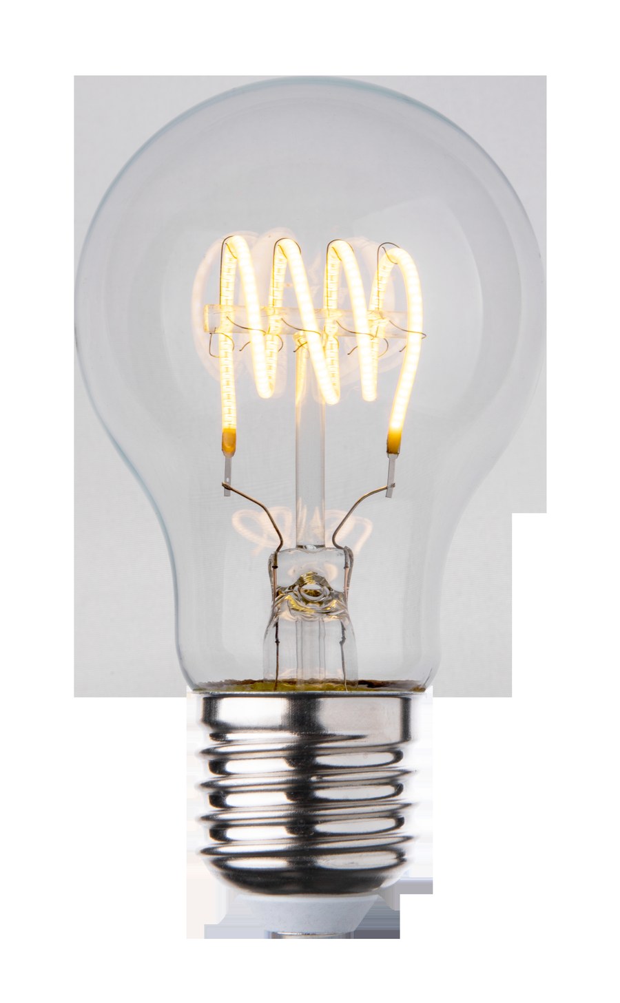
A flexible filament can be formed into loops, spirals, arcs, letters or other three-dimensional arrangements. Compared with straight rods, that freedom can change:
- the direction each emitting surface faces;
- spacing between bright segments;
- the apparent luminous area from each viewing direction;
- visual overlap among filaments, supports and reflections;
- the distribution of light through the glass envelope;
- the decorative pattern seen when the lamp is exposed.
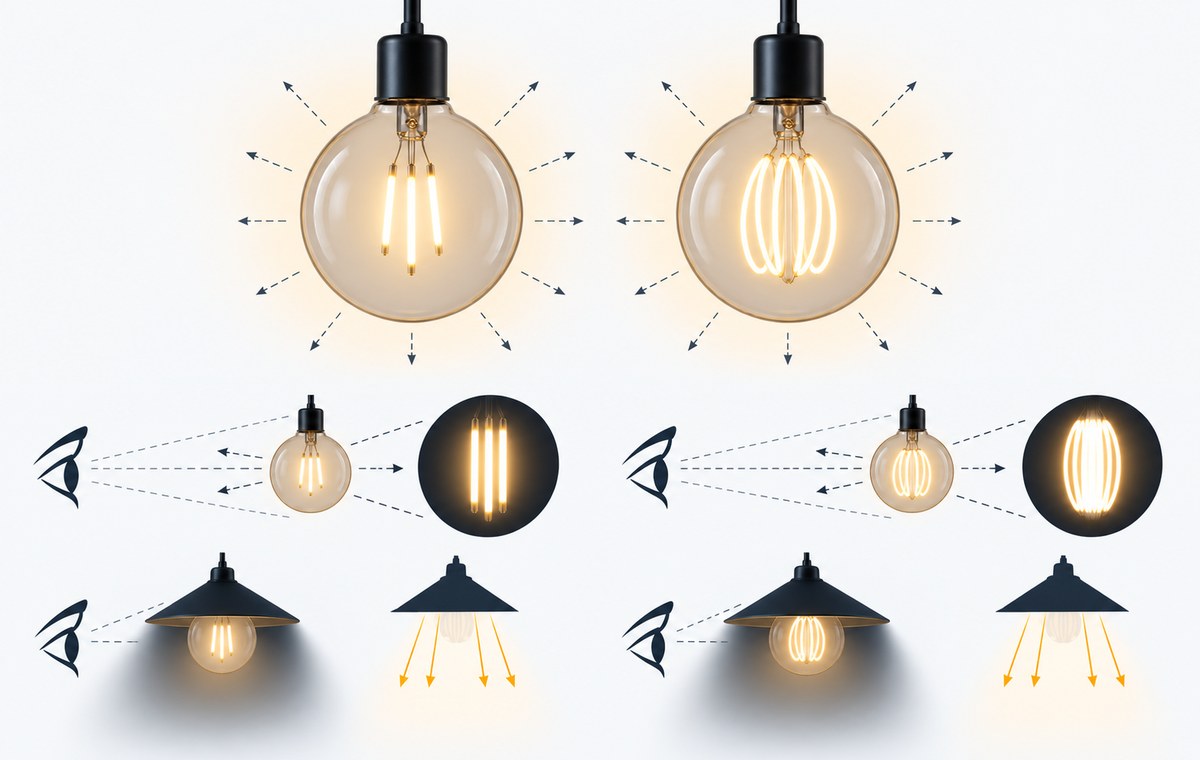
These are useful design controls. A curved arrangement may prevent every bright segment from facing the same direction, or it may create a larger and more continuous pattern from a selected view. But geometry can also work against comfort. A spiral may stack several bright sections in one line of sight, while a narrow curved strip can still have high local luminance.
The key mechanism is not softness or flexibility. It is how the final three-dimensional arrangement changes the luminance image seen by the observer.
Lumens and Luminance Answer Different Questions
Lumens describe total luminous flux. Luminance describes light leaving an apparent surface in a particular direction and is more closely related to how visually intense a source appears. Two bulbs can therefore deliver similar lumens while presenting very different high-luminance patterns.
A clear bulb can expose narrow luminous lines. A frosted or opal envelope may spread the visible emission over a larger apparent area, although transmission and uniformity depend on the material and coating. Simply lowering output can also make a lamp look softer, but that may reduce useful illumination rather than improve the optical design.
Product photographs are unsuitable for measuring this difference. Exposure, white balance, tone mapping, bloom and screen brightness can make the same lamp appear smoother or harsher. Use controlled observation for screening and calibrated luminance imaging when a formal comparative claim is required.
Research summarized in CIE 232:2019 is relevant here. Conventional Unified Glare Rating uses average source luminance, yet CIE reports that this approach can underestimate discomfort from highly non-uniform LED sources. Its preferred correction method defines the glare-source area from a luminance image. CIE TN 014:2023 describes an HDR luminance-image setup for applying that method.
This does not turn one bulb photograph into a universal UGR value. UGR belongs to an indoor lighting system with defined observer, room and luminaire conditions. A decorative exposed lamp must still be evaluated in its actual visual context.
When Flexible Geometry Is More Likely to Help
Flexible geometry becomes a useful design option when it changes a specific visual problem rather than merely changing the lamp’s appearance. It is more likely to help when:
- the final arrangement reduces direct alignment of several bright segments with normal sightlines;
- the apparent luminous pattern is distributed over a larger area without sacrificing required illuminance;
- the envelope or fixture softens local peaks while preserving the intended decorative form;
- the lamp is viewed mainly from angles where the curved pattern avoids concentrated overlap;
- the output and dimming range suit the adaptation level of the space.
Even then, describe the outcome for the tested model and application. A loop that works inside one pendant may present a bright edge when the same lamp is mounted horizontally in a wall fitting.
When Flexibility Does Not Solve the Problem
The design label is unlikely to help when the source remains directly visible at high local luminance, several segments overlap in the dominant sightline, or a dark background increases contrast. It also cannot correct an unsuitable mounting height, an unshielded fixture near eye level or a chandelier placing many visible lamps in the field of view.
| Observed condition | Likely implication | Better next step |
|---|---|---|
| Bright segments remain distracting from normal seats | Local luminance or direct view is still too high | Compare a diffusing envelope, shielding or a lower suitable output |
| One angle is comfortable but another is harsh | Three-dimensional overlap changes with view | Test all routine sightlines and revise orientation or fixture choice |
| Lamp looks softer only when dimmed very low | Comfort may come at the cost of useful light | Measure task illuminance and reconsider source size or shielding |
| Multiple lamps feel harsher than one sample | Source count and visual repetition matter | Test the full cluster or a representative mock-up |
| A warm version feels different from a cool version | Several optical and electrical variables may have changed | Match output and geometry before attributing the result to CCT |
| Camera images look smooth but users report discomfort | Photography is hiding luminance peaks or context | Inspect in person and use calibrated measurement if needed |
The Envelope and Fixture Often Matter More
A clear envelope preserves the filament pattern and supports the classic decorative look, but it also leaves small bright elements directly visible. Frosted, opal, tinted or mirrored envelopes alter the apparent source, transmission and reflections. None should be described as anti-glare without a bounded comparison.
The fixture completes the optical system. A shade can block the direct view while directing light onto walls or a table. An opal globe can enlarge the apparent source. A clear pendant can introduce additional reflections. Mounting height and socket orientation determine which parts of the filament face the observer.
For restaurants, hotels and residential decorative spaces, review both daytime appearance and the darker evening scene. The residential and decorative lighting solution provides the broader application context; the bulb decision still needs the actual fixture, mounting position and sightlines.
Use a Matched Comparison Instead of a Label Comparison
A useful test holds the major variables steady and changes only what the decision is meant to evaluate.
- Select exact flexible and rigid candidates with the same bulb shape and base.
- Record envelope finish, filament count, geometry, rated output, CCT, power and dimming status.
- Install each candidate in the same fixture and orientation.
- Match measured output or illuminance as closely as practical.
- Mark normal seated, standing and circulation viewing positions.
- Observe the lamp under representative daytime, evening and dimmed scenes.
- Check direct views, reflections on glass or screens and overlap among multiple lamps.
- Record comfort observations separately from appearance preference.
- Check flicker and dimmer behaviour as independent acceptance items.
- Use calibrated luminance imaging when the project needs a defensible glare comparison.
Consider a three-lamp pendant above a dining table. A flexible spiral may look comfortable from the entrance but create overlapping bright bands for seated users. A rigid four-filament lamp may show distinct lines but remain behind the shade edge from the same seats. The correct choice follows the occupied sightlines, not the geometry label.
The same logic applies to a clear wall sconce near a mirror. A visually attractive filament pattern can produce a distracting reflected image even when the direct view is shielded. Test both direct and reflected paths.
Keep Dimming, Flicker and CCT Separate
Reducing output can reduce luminance and eye illuminance from a glare source, so dimming may improve comfort. However, the bulb and dimmer must operate together without unstable output, drop-out, noise or objectionable temporal light modulation. The U.S. Department of Energy notes that LED output can respond rapidly to current variations from driver and dimmer electronics, making flicker a separate measurement problem.
Color temperature can influence the atmosphere and subjective impression of a space, but it is not a shortcut for controlling source luminance. If two versions differ in CCT, they may also differ in output, phosphor, drive conditions or envelope. Choose CCT for the visual design, then evaluate glare under matched conditions.
For a broader distinction between lamp constructions, see filament LED versus standard LED bulbs. That comparison does not replace the application-specific glare test described here.
Build the Purchase Specification Around the Application
For an exposed decorative lamp, request the exact model, bulb shape, envelope, output, CCT, filament layout, dimming declaration and suitable operating orientation. Add drawings or controlled multi-angle images when the three-dimensional pattern matters.
For task-adjacent installations, include the required illuminance, typical eye positions, screen or mirror locations and fixture shielding. For hospitality projects using many lamps, test a representative cluster under the night scene. One sample on a bright workbench will not represent the installed adaptation level or source count.
The acceptance record should state:
- exact lamp and fixture identities;
- mounting height and orientation;
- dimmer model and test levels;
- observer positions and background conditions;
- required task illuminance;
- direct and reflected glare observations;
- flicker or stability observations;
- photographs used only as location records, not luminance proof;
- measurement method when a formal claim is needed;
- approved alternatives and change-control rules.
If you want New Lights to compare a specific configuration, send the exact lamp, fixture, output, dimmer and viewing requirements. That evidence is enough to define a useful sample plan instead of relying on the word “flexible.”
Frequently Asked Questions
Do flexible LED filaments automatically reduce glare?
No. Flexibility expands the available geometry, but the final luminance pattern, envelope, output, fixture, observer position and background determine the result.
Is a frosted flexible-filament bulb always more comfortable than a clear one?
No. Frosting can enlarge and smooth the apparent source, but transmission, uniformity and useful light must be compared at matched conditions.
Does adding more filament length reduce local brightness?
Only if the complete electrical and optical design distributes emission that way. More length or more segments can also create additional overlap from some views.
Can a bare filament bulb have one universal UGR value?
UGR is evaluated for a defined indoor lighting system, observer position and room. Highly non-uniform sources also require careful source-area treatment, so a standalone value needs a clearly stated scope.
Can dimming fix glare?
Dimming may reduce source luminance, but it can also reduce useful light and introduce compatibility or flicker problems. Test the exact lamp, dimmer and operating range.
Editorial Sources
- Illuminating Engineering Society, “Glare”: https://ies.org/definitions/glare/
- Illuminating Engineering Society, “Luminance”: https://ies.org/definitions/luminance/
- CIE 232:2019, “Discomfort Caused by Glare from Luminaires with a Non-Uniform Source Luminance”: https://www.cie.co.at/publications/discomfort-caused-glare-luminaires-non-uniform-source-luminance
- CIE TN 014:2023, “Example Luminance Measurement Setup for UGR”: https://cie.co.at/publications/example-luminance-measurement-setup-ugr
- U.S. Department of Energy, “Achieving Better Measurement of Discomfort from Glare”: https://www.energy.gov/cmei/ssl/articles/achieving-better-measurement-discomfort-glare
- U.S. Department of Energy, “Flicker Research”: https://www.energy.gov/cmei/ssl/flicker-research