A temperature such as 100°C cannot answer whether a painted bulb coating will crack, detach or change color over time. Durability belongs to the complete system: the substrate, preparation, primer, color coat, film thickness, cure, actual part temperature, thermal cycling and surrounding environment.
The practical decision is to qualify a specified coating process on representative finished parts against a defined operating profile. Measure the part before and after exposure, set acceptance limits before testing, and keep appearance results separate from electrical or product-safety approval.
Start With the Exact Coating System
Names such as acrylic, epoxy, polyurethane or silicone identify broad material families, not a finished-part temperature rating. Formulations within the same family can use different binders, pigments, fillers, additives and cure mechanisms. Application conditions can change the final film just as much as the product name.
Before discussing heat resistance, lock the identity of every layer and process step:
- substrate material and grade;
- cleaning and surface-preparation method;
- pretreatment and primer, if used;
- color-coat manufacturer, product code and batch;
- target dry-film thickness and allowed range;
- flash-off and cure schedule;
- rework method and permitted number of coats.
ISO 3248:2016 describes a method for determining how a coating system responds to a specified temperature, including changes in gloss or color and defects such as blistering, cracking or detachment. Its scope illustrates the central point: the test applies to a defined coating system under stated conditions, not to an unspecified paint name.
Match the Test Method to the Substrate
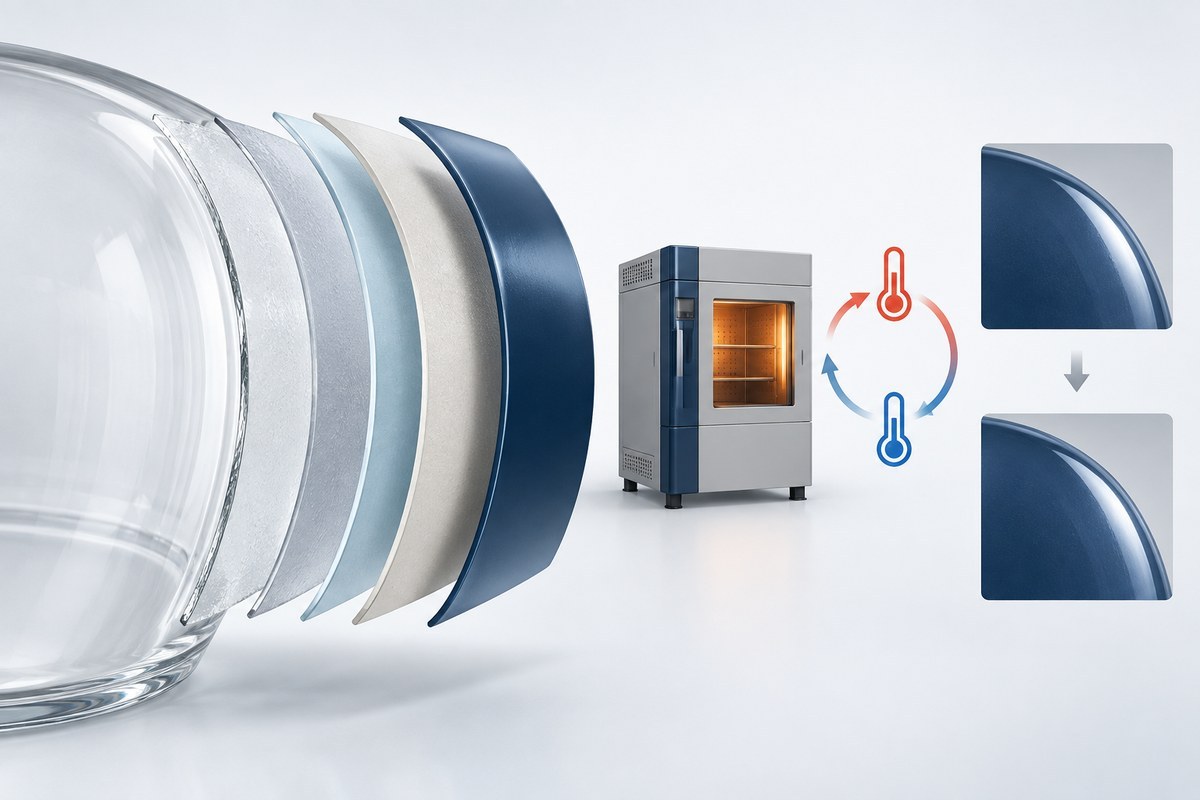
The interface between the coating and the part is often where failure begins. Oil, dust, moisture, oxide, release agent or handling residue can reduce adhesion. Glass, steel, aluminum and polymers also respond differently to cleaning, abrasion, chemical pretreatment and heat.
ASTM D2485-22 evaluates heat-resistant coatings applied to steel surfaces. It can help frame elevated-temperature testing for that substrate, but its scope should not be extended automatically to a glass bulb envelope or a polymer lamp part. The specimen, preparation and method must match the actual construction.
ASTM D3359-23 uses tape-test procedures to rate adhesion of relatively ductile coatings on metallic substrates. ASTM notes that the method indicates whether a minimum adhesion level is met; it does not provide an absolute bond-strength value or distinguish fine differences at high adhesion. Operator technique, tape, temperature and humidity can affect the result. Curved, brittle, transparent or nonmetallic parts may require another agreed method.
| Part or evidence | What it can establish | What remains to be defined |
|---|---|---|
| Coating supplier data sheet | Candidate material limits and application instructions | Whether the exact finished part meets project criteria |
| Prepared flat panel | Formulation and process screening on a controlled substrate | Curvature, local film build and lamp-specific thermal conditions |
| Representative finished bulb or part | Behavior of the specified construction under the test profile | Production variation and long-term process control |
| Adhesion rating | Condition of the film-to-substrate or intercoat interface | Color, gloss, cracking, emissions and electrical safety |
| Appearance inspection | Visible defects under the chosen inspection conditions | Hidden interface damage and unrelated product requirements |
This evidence ladder prevents a common shortcut: treating a material data sheet or one flat-panel result as proof for every painted bulb geometry.
Measure the Temperature the Coating Actually Sees
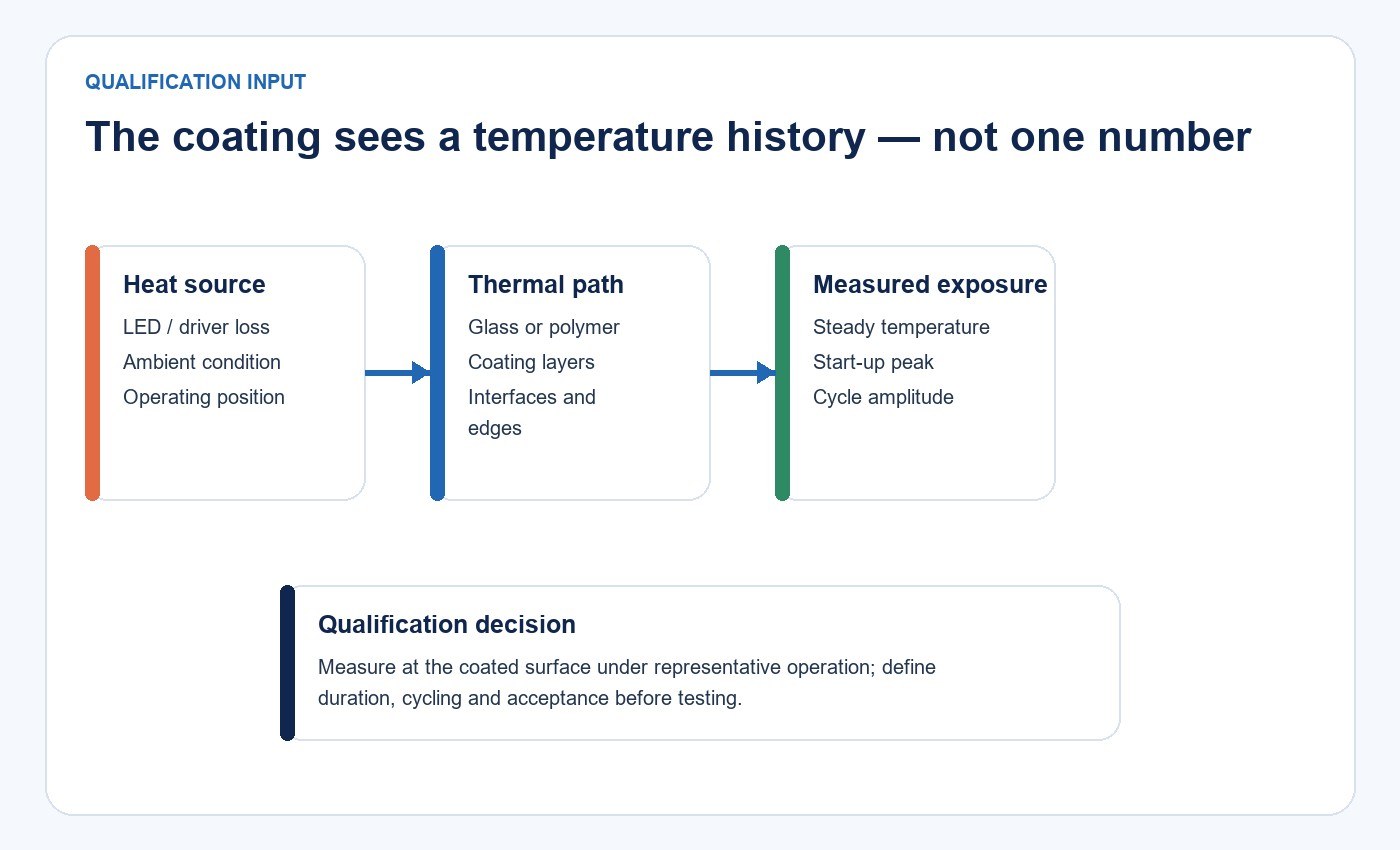
Lamp wattage and ambient temperature do not state the coating temperature. Heat can concentrate near the light engine, cap, driver, adhesive joint, support structure or a restricted-airflow region. Orientation, enclosure, socket, voltage, dimming state and nearby surfaces may change the temperature map.
A useful test plan begins with representative assemblies operated in the intended configuration. Record the model, input condition, ambient temperature, airflow, mounting orientation, enclosure and stabilization criterion. Identify measurement points and attachment methods so another technician can reproduce the map.
Do not base the exposure profile on one convenient measurement point. The hottest coated region may be small, and the location may shift when the lamp is mounted base-up, enclosed or operated at a different setting. Where several configurations are allowed, test the worst permitted combination or define which configurations are excluded.
The related LED thermal management and lifetime validation guide explains how to separate temperature measurements, component evidence and complete-product lifetime claims.
Separate Continuous Heat, Peaks and Thermal Cycling
A coating may tolerate a short excursion but change during a long hold. It may also remain stable at a steady temperature yet fail after repeated heating and cooling. The coating and substrate expand at different rates, so every cycle can add interfacial or film stress.
Define the exposure profile in terms that can be reproduced:
- continuous operating temperature and duration;
- permitted peak temperature and peak duration;
- heat-up and cool-down rates;
- high- and low-temperature dwell periods;
- number of cycles;
- powered or unpowered condition;
- inspection and conditioning intervals;
- humidity, UV or cleaning exposure where the application requires it.
A short powered observation is useful for finding early defects, but it should not be converted into years of expected service without a validated acceleration relationship. A pass means only that the specimen met the agreed criteria for the stated profile.
Define Failure and Acceptance Before Testing
“No cracking or fading” is not precise enough for supplier approval. Two inspectors may disagree about a hairline crack, edge lift, gloss change or color shift. The test plan should name each failure mode, how it is measured and the maximum acceptable change.
| Failure mode | Inspection or measurement | Decision question |
|---|---|---|
| Cracking, crazing or blistering | Controlled visual inspection with defined lighting and magnification | Is any defect allowed, and over what area? |
| Detachment or edge lifting | Agreed adhesion method before and after exposure | What rating is required at each stage? |
| Color change | Instrumental measurement at fixed locations plus visual review | Which color equation and tolerance apply? |
| Gloss change | Same geometry, instrument and conditioning before and after exposure | What change affects the intended appearance? |
| Softening, transfer or tack | Defined contact or hardness method at a stated conditioning time | Must the surface recover after cooling? |
| Odor, residue or interaction | Application-specific material and safety review | Does the condition trigger additional testing? |
ASTM D2244-25 covers calculation of small color differences from instrumentally measured color coordinates. It also makes the purchaser-seller agreement important: the same numerical difference may not have the same commercial meaning across colors, gloss levels and textures. Select the color space, illuminant, observer setting, measurement geometry, locations and tolerance before viewing the result.
Photographs can support the record when camera position, lighting, exposure, scale and color reference are controlled. They are less reliable when “before” and “after” images use different white balance or reflections. Instrument data and a controlled visual assessment should answer different parts of the acceptance question.
Build a Representative Qualification Protocol
A robust protocol connects four elements: specimen identity, exposure, measurements and acceptance limits.
- Choose representative specimens. Use production-intent substrate, coating batches, film build, cure and rework rules. Include enough samples to reveal normal variation rather than relying on one unusually good part.
- Record the baseline. Capture appearance, color, gloss, adhesion and film thickness where each measure is applicable. Mark measurement locations so the same areas are checked later.
- Apply the defined exposure. Reproduce or conservatively bound the actual temperature profile, orientation and environmental conditions.
- Condition and remeasure. State how long the part cools or recovers before each inspection. Compare every result with the pre-agreed criterion.
- Investigate failures and deviations. Record failed samples, process deviations, retests and any material or process change. Do not merge a changed construction into the original result.
Consider a decorative globe intended for an enclosed fixture. A bench test in open air may show an acceptable coating temperature, while the enclosed fixture produces a higher cap-adjacent hot spot. If the product can also be installed base-up, that orientation may alter internal heat flow again. The qualification matrix should either cover those allowed conditions or make the exclusions explicit. This is why a single “100°C resistant” sentence is less useful than a reproducible operating envelope.
Control Production After Qualification
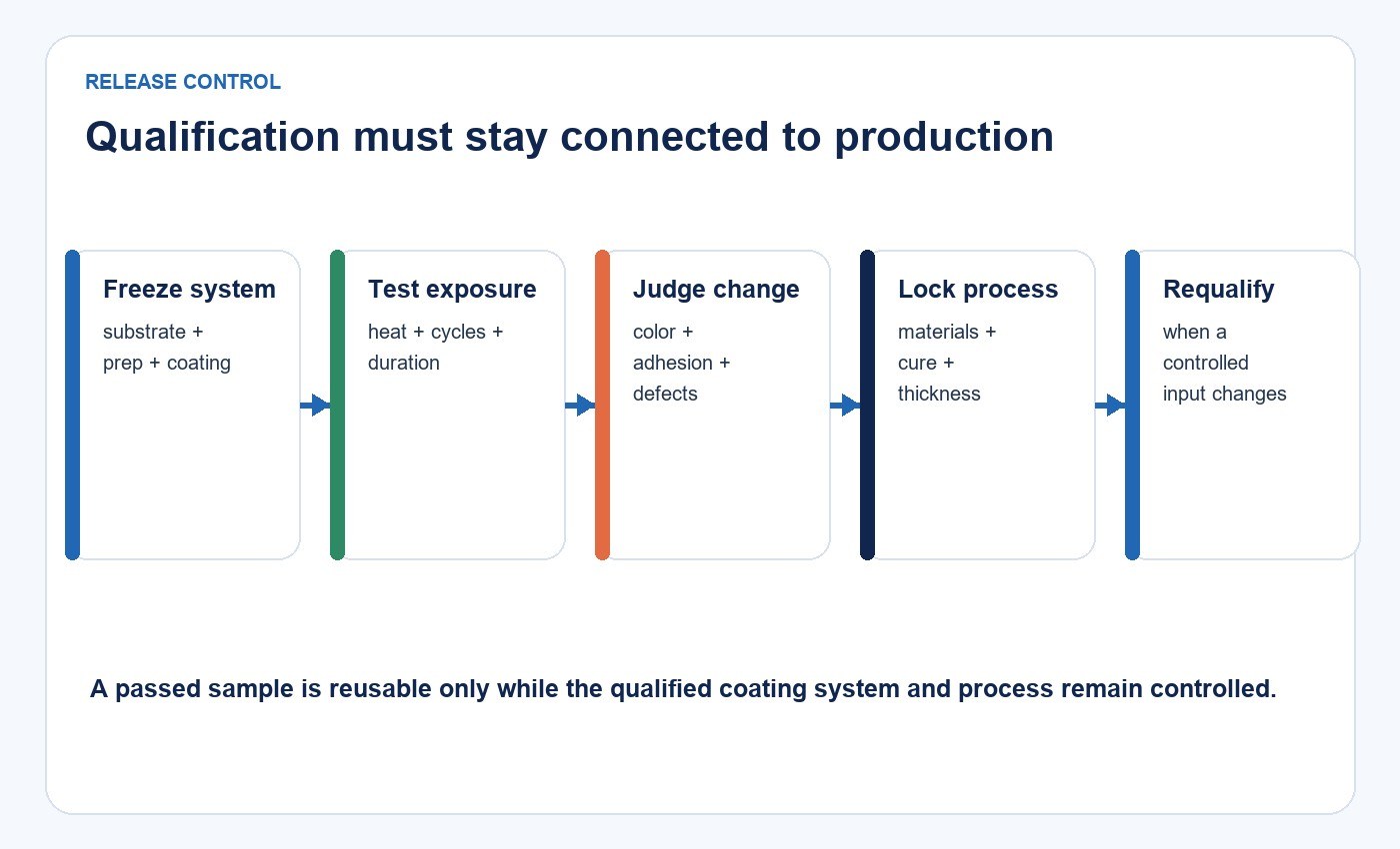
Qualification answers whether defined specimens met defined criteria. Production control asks whether later lots still represent those specimens.
Useful controls may include coating identity and shelf life, substrate cleanliness, viscosity or solids where relevant, spray parameters, flash time, dry-film thickness, cure profile, appearance inspection and periodic adhesion or thermal checks. Pigment, binder, primer, substrate, equipment, cure or rework changes should trigger review because they can change thermal behavior even when the visible color initially matches.
For a broader product selection, browse the LED bulb category and the residential and decorative lighting solution. Model selection should follow the published product data and a representative sample; this coating guide does not replace either.
Keep Appearance Durability Separate From Product Safety
A coating can remain attached and visually acceptable while other product risks remain unresolved. Elevated temperature may affect emissions, flammability, electrical insulation, light transmission, adhesives or nearby components. Applicable requirements depend on the material location, product construction and destination market.
Use coating heat tests to answer coating questions. Electrical, fire, chemical and product-certification decisions require their own applicable standards, qualified testing where required and records tied to the exact construction.
Supplier Evidence Checklist
Before approving a painted bulb or lamp component for elevated-temperature service, request:
- exact part, substrate and surface-preparation specification;
- coating manufacturer, product code, color, primer and layer sequence;
- target dry-film thickness and production tolerance;
- cure schedule and actual part-temperature record;
- finished-part temperature map and intended duty cycle;
- heat-hold and thermal-cycle protocol with sample count;
- baseline and post-exposure photos, adhesion, color, gloss and defect records;
- acceptance limits and treatment of nonconforming samples;
- environmental and safety evidence required by the application;
- production checks, traceability and change-control rules.
If you are preparing a coating qualification requirement, contact New Lights with the part, substrate, coating specification, operating conditions and available test records.
Frequently Asked Questions
Is 100°C automatically too hot for a painted bulb coating?
No universal conclusion follows from that temperature alone. The outcome depends on the complete coating system, exposure duration, cycling, substrate and environment. Test representative parts against agreed criteria.
Does a high-temperature paint data sheet qualify the finished bulb?
No. It is screening evidence. Confirm what the supplier rating means, then validate the specified coating as applied to the actual part under the lamp’s thermal profile.
Is a 72-hour powered test enough?
It can reveal early defects, but it does not by itself predict long-term service. Use it as a defined screening step unless a broader qualification and validated acceleration model support a longer-term conclusion.
How should color change be evaluated?
Use controlled visual conditions and, where appropriate, instrumental measurements at fixed locations. Agree on the calculation method, measurement settings and acceptable difference before testing.
Why can cycling cause damage when steady heat does not?
The coating and substrate may expand and contract by different amounts. Repeated temperature changes can build stresses that a constant-temperature hold does not reproduce.
Editorial Sources
- ISO 3248:2016, Paints and varnishes — Determination of the effect of heat: https://www.iso.org/standard/64818.html
- ASTM D2485-22, Standard Test Methods for Evaluating Coatings For High Temperature Service: https://store.astm.org/d2485-22.html
- ASTM D3359-23, Standard Test Methods for Rating Adhesion by Tape Test: https://store.astm.org/standards/d3359
- ASTM D2244-25, Standard Practice for Calculation of Color Tolerances and Color Differences from Instrumentally Measured Color Coordinates: https://store.astm.org/d2244-25.html