An emergency T8 LED tube should be evaluated as a multi-state system. Test it on normal AC, capture the mains-loss changeover, monitor the complete battery discharge, restore power and confirm recharge behavior. A stable normal-mode reading—or a “non-flicker” specification line—covers only the operating condition and method identified with that result.
The practical objective is a time-aligned record of electrical input and light output for the exact tube, emergency driver, battery, wiring and fixture configuration. That record shows whether the system meets the project’s own transition, duration and temporal-light requirements.
Confirm the Emergency Tube Architecture First
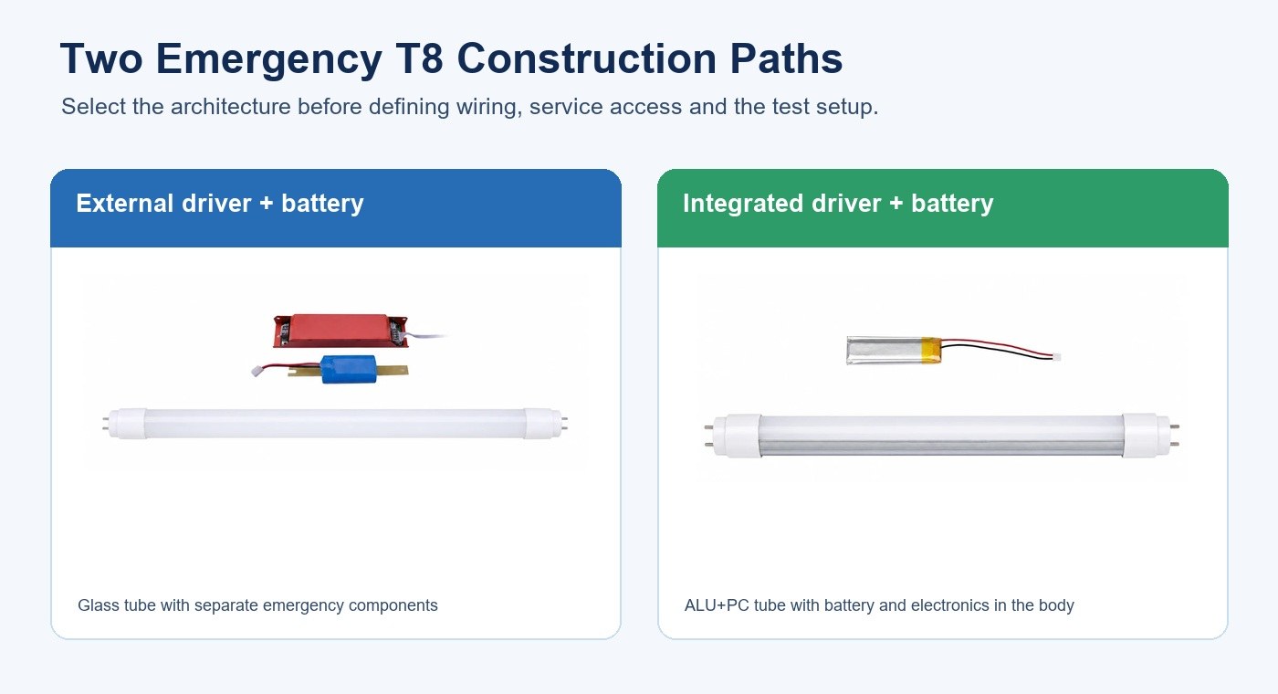
Emergency T8 products can place the battery and emergency electronics outside the tube or integrate them into the tube body. This distinction changes wiring, space, service access, thermal conditions and the test boundary.
The current New Lights Emergency T8 LED Tube page presents two constructions. One uses a glass tube with a separate red emergency driver and external battery. The other uses an ALU+PC tube with the driver and battery in the body. The published family covers 590, 895, 1199 and 1499 mm lengths at 9, 12, 18 and 22 W.
| Architecture decision | External driver and battery | Integrated driver and battery |
|---|---|---|
| Installation space | Requires a defined location for separate components | Requires clearance for the complete tube body and end connections |
| Service task | Tube, driver and battery may be identified separately | Replacement and service rules follow the integrated assembly |
| Test access | Individual component points may be accessible | Measurement access must be planned around the assembled lamp |
| Change control | Track tube, emergency driver and battery references | Track the complete integrated configuration and battery reference |
Do not transfer results between these architectures. Even two tubes with the same nominal length and mains power can use different emergency circuits, batteries and thermal paths.
Define the Performance Boundary Before Testing
Translate “flicker-free emergency lighting” into measurable conditions. State the normal-mode operating point, permitted interruption during changeover, emergency output target, required duration, acceptable modulation metrics and the restoration behavior. Also record voltage, ambient temperature, battery state, fixture, control gear and measurement method.
The phrase emergency output needs a reference. It may mean a percentage of normal luminous flux, measured illuminance at a defined point or another project-specific value. A percentage without its denominator and test geometry cannot be used as an acceptance criterion.
| Requirement | Define explicitly | Why it matters |
|---|---|---|
| Normal mode | Supply, fixture, controls and stabilized output | Creates the baseline |
| Changeover | Trigger, maximum interruption and settling time | Captures a short event that steady readings miss |
| Emergency level | Measurement quantity, location and reference | Prevents ambiguous percentage claims |
| Duration | Required time and minimum end-of-test output | Tests battery-supported performance through the full interval |
| Temporal light | Metric, instrument, bandwidth and sampling | Makes flicker results comparable |
| Recovery | Return-to-normal behavior and recharge condition | Finds repeated restart or charging interactions |
For broader selection questions such as maintained versus non-maintained operation and centralized versus self-contained arrangements, start with the emergency lighting system selection guide. For component sizing and record control, use the emergency driver and battery planning guide.
Establish the Normal-Mode Baseline
Begin with the battery in the specified initial condition and the lamp installed in the intended fixture. Stabilize the system before recording input voltage, current, power and light output. If the project includes dimming, sensors or a building control interface, test the normal operating points that can actually occur.
Capture the light waveform rather than relying only on a phone camera. Temporal light modulation depends on the driver, load, dimming method and waveform; power factor, THD and flicker describe different behavior and cannot substitute for one another. The flicker, power factor and THD buyer checklist explains how to separate those measurements.
Normal-mode stability is necessary, but it is only the first state in the sequence.
Test Every Operating State
Use one synchronized clock for electrical and optical channels. Record the system before mains loss, through changeover, during battery operation, through restoration and into recharge. This makes it possible to distinguish a planned output step from an unintended interruption, restart or modulation event.
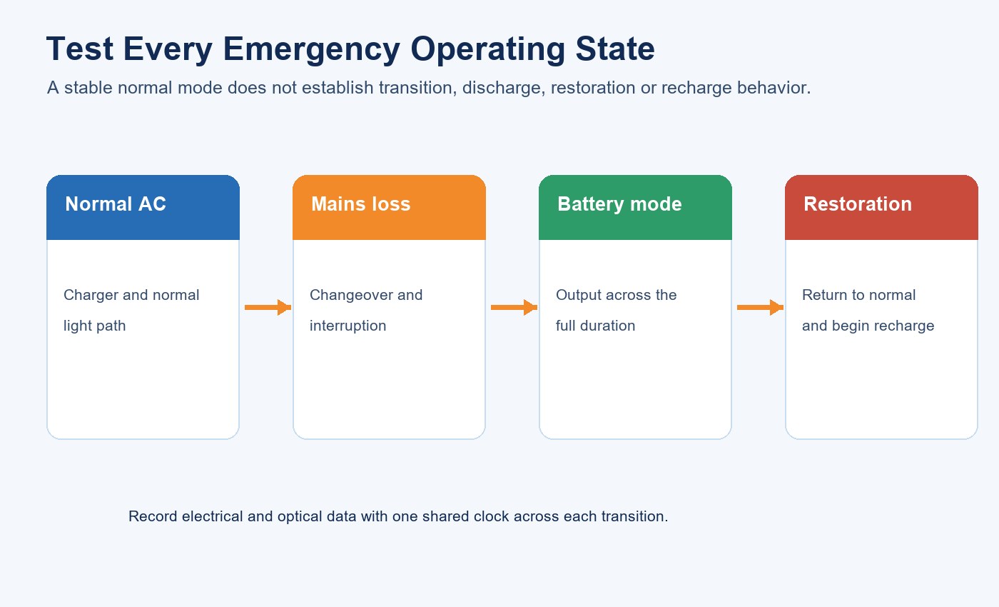
Repeat the sequence enough times to reveal inconsistent transfer behavior. If controls, relays or upstream emergency equipment can create more than one loss-of-power condition, include each defined condition rather than testing only a convenient wall-switch event.
Capture the Mains-Loss Transition
A handheld lux meter can show the output before and after transfer but may miss what happens between those readings. Use synchronized waveform or high-rate logging when interruption and settling time matter. Record the exact moment the mains supply is removed and identify the first stable emergency level.

Separate four observations:
Intended Output Step
Emergency mode may intentionally run below normal output to preserve battery duration. This level change is not itself evidence of flicker, but it must match the project’s defined emergency-output criterion.
Interruption and Settling
Measure how long light output falls below the permitted level and how long the emergency circuit takes to stabilize. A short dropout, overshoot or repeated restart can be hidden by slow instruments.
Repetitive Modulation
Once the emergency state is stable, evaluate the waveform using the selected temporal-light metrics. Keep instrument bandwidth, sampling rate and analysis window with the result.
Transition Repeatability
Run multiple changeovers from a controlled battery state. Variation between runs can point to relay behavior, battery condition, protection logic, wiring or thermal state.
Monitor the Complete Battery Discharge
An acceptable first minute can still be followed by drift or unstable behavior later in the required duration. Record light output and electrical behavior at defined intervals, then increase sampling density near the end of discharge where battery voltage and control behavior may change more quickly.
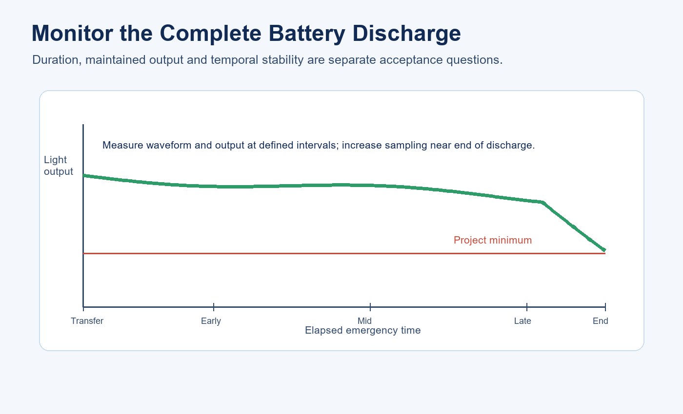
The current product page describes two configuration-dependent duration examples: 90 minutes for the external system after full charge and 60 minutes for the integrated system after an eight-hour charge. Treat these as starting points for the named configuration, not as a universal family result. The purchase specification should identify the exact construction, battery, charging condition, emergency level and required duration.
| Test stage | Minimum record | Decision question |
|---|---|---|
| Transfer | Time of mains loss, interruption and first stable emergency level | Did the lamp enter emergency mode as required? |
| Early discharge | Output, waveform, battery voltage and temperature | Is initial operation stable? |
| Mid discharge | Same channels at controlled intervals | Is output drifting or modulation increasing? |
| Late discharge | Denser sampling before the required endpoint | Does the system remain above the project minimum? |
| End and shutdown | Time, output, protection behavior and final battery condition | Is duration achieved without unstable cycling? |
If a sample is being approved for procurement, preserve the tube code, emergency driver reference, battery reference, production label and test setup. The LED lighting sample evaluation checklist provides a broader record for comparing supplier samples.
Restore Mains Power and Verify Recharge Behavior
Restoration is another transition, not merely the end of the test. Record the return from emergency level to normal output, check for repeated switching or restart and confirm the charging path begins as intended. If the system can be exposed to rapid power cycling, include the relevant sequence.
After the specified recharge period, repeat a controlled emergency test. This checks whether the charging process restores usable duration and whether the system behaves consistently after a full cycle. Keep recharge time, ambient temperature and any indicator status in the record.
Isolate the Cause of Unstable Light
When a waveform or visible symptom fails the acceptance limit, change one variable at a time. Randomly replacing several components may make the symptom disappear without establishing the cause.
Emergency Driver and Load Match
Confirm that the emergency driver is intended for the exact lamp load and wiring arrangement. A mismatch can affect regulation, transfer behavior and discharge stability.
Battery State and Voltage Sag
Compare a controlled charged state with later points in discharge. If modulation or cycling appears only as battery voltage falls, inspect battery condition, connections, protection thresholds and driver regulation together.
Fixture Wiring and Control Interaction
Verify permanent and switched supplies, lampholders, polarity where applicable, relay contacts, sensors and upstream emergency controls. The LED tube installation guide covers retrofit wiring boundaries; emergency configurations require the exact product instructions and qualified electrical review.
Thermal Conditions
Measure relevant component and ambient temperatures during normal operation, battery discharge and recharge. Integrated electronics and batteries may experience a different thermal environment from external components.
Use Camera Screening Carefully
A phone camera can reveal banding or pulsing that deserves investigation, but exposure time, frame rate, rolling shutter and image processing can also create or hide patterns. Use camera observations to locate a condition, then confirm it with a defined optical measurement.
Record the operating state when the symptom appears. A lamp that looks stable on mains power may behave differently during transfer, late discharge or recharge. Do not combine results from different states under one “flicker-free” conclusion.
Build a Three-Stage Acceptance Record
The most useful approval record separates specification review, controlled sample testing and production verification.
| Stage | Evidence to retain | Release decision |
|---|---|---|
| Specification | Architecture, wiring, emergency level, duration, metrics and component references | Is the offer testable and unambiguous? |
| Sample | Time-aligned normal, transfer, discharge, restoration and recharge results | Does the named sample meet the project limits? |
| Production | Approved references, incoming checks and change-control record | Does delivered production remain equivalent to the approved sample? |
For market-specific documentation, certification and installation boundaries, consult the LED tube global compliance guide and the applicable project authority. A laboratory result is meaningful only when its configuration and test conditions match the offered product.
Plan Maintenance and Change Control
Battery age, driver revision, LED load, wiring and thermal conditions can change emergency behavior. Define inspection and periodic test responsibilities, replacement intervals according to the approved system, spare-part identity and the action required after any component change.
Use the lighting maintenance and spare-parts planning guide to structure installed-base records. For a new order, request a controlled bill of materials, label format and revision process; the New Lights factory and manufacturing capability page outlines the broader production and quality context.
Prepare the RFQ and Test Brief
Send the supplier the required architecture, length, power, supply, emergency level definition, duration, fixture and wiring context, transition limit, temporal-light metrics, ambient boundary and documentation list. Ask for the exact tube, driver and battery references that will appear on the quotation, sample and production order.
To review an Emergency T8 configuration, contact New Lights with the project market, fixture, wiring diagram, required duration and acceptance method.
Frequently Asked Questions
Does a non-flicker specification cover emergency mode?
Not automatically. Confirm the scope of the claim and test normal AC, changeover, battery discharge, restoration and recharge for the exact configuration.
Is a lower emergency output the same as flicker?
No. A planned step to a lower steady level and repetitive temporal modulation are different observations. Both may need limits, but they should be measured separately.
Can a phone camera approve an emergency tube?
No. It is useful for screening, but camera settings can create or hide banding. Use a defined optical measurement for acceptance.
When should flicker be checked during a duration test?
Check the transition and stable emergency operation, then repeat measurements at controlled intervals through the required duration, especially near the end of discharge.
Can test results be reused after changing the battery or driver?
Only after the change is reviewed against the approved configuration and its effect is verified. Driver, battery, load and wiring changes can alter transition, duration and temporal-light behavior.