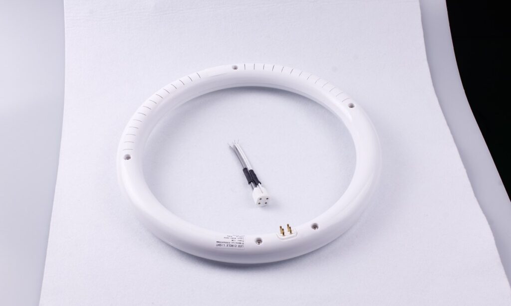
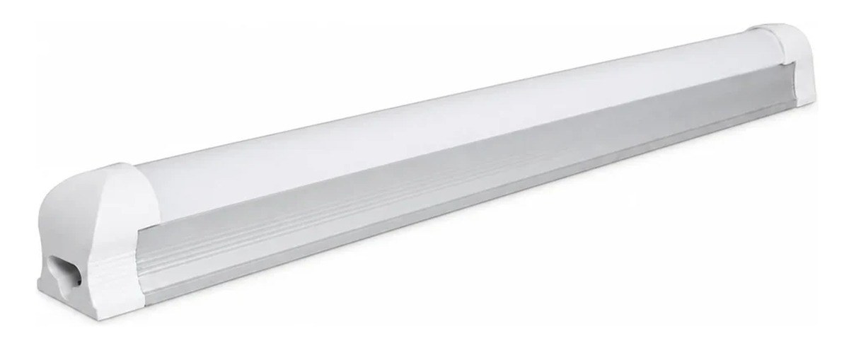
A T8 integrated LED fixture combines the LED board, driver, diffuser, housing, end caps, mounting hardware and connection interfaces into one supplied luminaire. It is not a replacement T8 tube fitted into a separate fluorescent fixture. That distinction changes the drawings, wiring checks, linked-load calculation, optical approval and maintenance plan required for a project.
The practical question is not whether integration is inherently better. It is whether the exact fixture configuration fits the application and whether the complete electrical, mechanical and optical system has been documented. Start by confirming the product category, then approve the model, feed method, linked-run limit and service boundary together.
Identify the Product Before Comparing Specifications
Linear products with similar proportions can belong to different system categories. A replaceable LED tube depends on a host fixture and lampholders. An integrated batten or T8-form fixture includes its own source and driver. A retrofit kit modifies an existing body. An under-cabinet light may use a different mounting, linking and control approach again.
The current New Lights Surface-Mounted T8 Integrated LED Fixture uses SMD 2835 LEDs behind a wide diffuser, an IC driver, metal mounting clips and male/female connector options. Published construction options include ALU+PC and full-PC bodies, with an optional switch. Treat each quoted configuration as a complete luminaire rather than assuming compatibility with fluorescent lampholders or ballasts.
| Product category | What is supplied | Existing fixture dependency | Typical maintenance boundary |
|---|---|---|---|
| Integrated LED fixture | Source, driver, optics, housing and mounting interfaces | None beyond the mounting surface and branch wiring | Approved component service or complete-fixture replacement |
| T8 LED replacement tube | Lamp with internal or external driver arrangement | Lampholders, wiring and sometimes ballast | Replace lamp; verify host-fixture compatibility |
| Fluorescent batten | Housing, ballast, lampholders and fluorescent lamp | Complete legacy system | Lamp, ballast or fixture service |
| Retrofit kit | Defined replacement components | Existing housing retained | Depends on kit listing and installation instructions |
Use the LED tube versus fluorescent tube guide when the project actually involves replaceable lamps. For compact furniture or display lighting, the under-cabinet lights versus linear fixtures comparison helps separate installation categories.
Define the Integration Boundary
“Integrated” describes the supplied product boundary, not a promise that every internal part is permanently bonded or field replaceable. The driver may be concealed but accessible, or it may require factory service. The LED board may be screwed, clipped, bonded or enclosed in a way that makes whole-unit replacement the approved repair. Appearance alone cannot establish the service method.
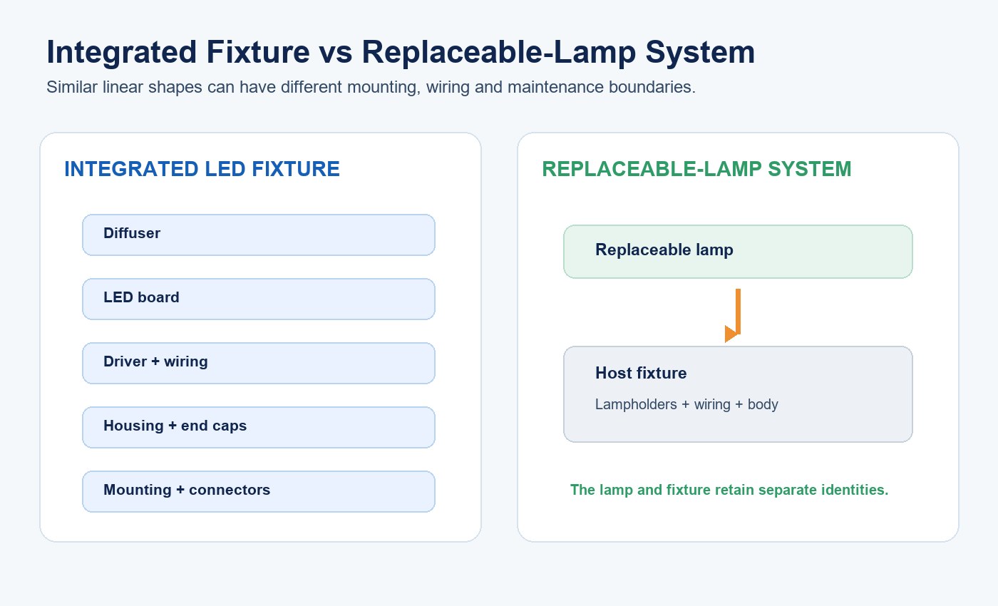
Request a product drawing that identifies the diffuser, LED board, driver, conductors, housing, end caps, connectors, switch, mounting clips and fasteners. The drawing should distinguish factory-only parts from approved field-service parts. Link it to a bill of materials and revision so that later substitutions can be assessed.
This boundary matters because a change to the LEDs, driver, diffuser or body can affect input power, output, distribution, color, temperature and temporal light modulation. A sample is representative only when its critical components and configuration match the production order.
Freeze the Exact Variant Before Testing
The product family includes different lengths and slash-listed power versions. A slash value should not be interpreted as field-selectable power unless the model code, switch function and test evidence explicitly say so. It may instead represent separate orderable variants.
Record every value that changes the supplied system: length, nominal power, input range, body construction, color temperature, diffuser, connector, switch, controls and accessories. If a switch is present, establish whether it controls power, CCT, on/off operation or another function.
| Configuration field | Evidence to request | Why it affects approval |
|---|---|---|
| Length and body | Dimensioned drawing and construction code | Changes mounting, stiffness and thermal path |
| Power and input | Model code, label and electrical report | Determines current, linked load and circuit planning |
| LED and driver | Controlled BOM or approved component list | Affects output, power quality, temperature and lifetime evidence |
| Diffuser and finish | Material and optical version | Changes transmission, distribution and visible source image |
| Connector and switch | Pinout, rating and operating instructions | Defines feed direction, linking and permitted control behavior |
| Market configuration | Marking and certificate scope | Prevents applying evidence to an uncovered version |
Verify the Feed and Wiring Architecture
The published product information identifies single-end input. The project documents should show which end receives supply, which conductors pass through the body, how connectors are keyed and whether the opposite connector is an output only. Confirm voltage, frequency, grounding or insulation class, conductor size, polarity where applicable, strain relief and the permitted feed direction.
Do not design from connector shape alone. Two connectors that physically mate may have different pin assignments, ratings or intended systems. Mixing families can create reversed polarity, missing earth continuity or an underrated connection. Specify matching cable and connector part numbers with the fixture.
If the row includes switches, sensors, dimming or emergency equipment, verify the wiring for that exact arrangement. A switched fixture in the middle of a linked run may interrupt only its own light source or may affect downstream supply, depending on the internal circuit. The diagram must resolve this before installation.
Calculate the Linked Run as One Electrical Path
Multiple-connection capability does not mean unlimited daisy chaining. Every downstream fixture adds current through the upstream feed cable, connector contacts, pass-through conductors and first fixture. The permitted quantity is therefore bounded by more than the branch breaker.
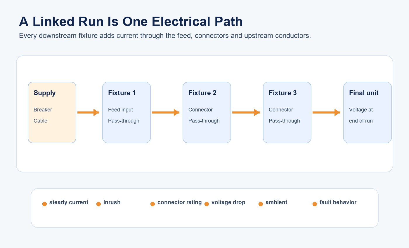
For an initial steady-state estimate, divide the total rated input power by the supply voltage and adjust for the applicable power factor and design conditions. That estimate is not the final limit. Compare it with connector and conductor ratings, protective-device behavior, inrush current, voltage drop, ambient temperature and the manufacturer’s model-specific maximum.
The first limiting condition may be connector current, accumulated inrush, conductor temperature or end-of-run voltage rather than total watts. A 230 V run and a 120 V run carrying the same total power do not draw the same current. Different power variants also change the answer.
| Linked-run check | Input required | Release criterion |
|---|---|---|
| Steady current | Actual system power, voltage and power factor | Below the approved cable, connector and pass-through ratings |
| Inrush | Driver inrush profile and protective device | Reliable start without nuisance operation or contact stress |
| Voltage drop | Length, conductor size, connector count and load | Final fixture remains within its approved input range |
| Thermal condition | Ambient, mounting and continuous load | Connector, conductor and driver temperatures remain acceptable |
| Fault behavior | Feed arrangement and protective coordination | Fault isolation follows the approved design |
The T5 integrated fixture linking guide explains the same calculation discipline for another product family; do not transfer its numerical limits to a T8 fixture.
Coordinate Mounting and Connector Alignment
Define mounting orientation, clip spacing, substrate, fasteners, clearances and cable routes on the installation drawing. Long fixtures can show bowing or uneven diffuser lines when clips are too far apart or the surface is not flat. Connector clearance must be available before the row is pushed into place.
Linked units also need mechanical alignment. Use the connector to make the electrical interface, not to pull misaligned housings into a straight line. Forcing the joint can load contacts, crack end caps or make future removal difficult. Check each fixture independently against the project datum before closing the connection.
Inspect end caps, clips, strain relief and the joint after installation. If a continuous appearance is important, approve the gap, diffuser alignment and color consistency in a representative row rather than in a single loose sample.
Evaluate the Complete Optical System
The LED package does not determine delivered light by itself. The board position, diffuser transmission, housing geometry and mounting location shape distribution, luminance and glare. Review complete-fixture photometry for the important model and configuration rather than relying on LED efficacy or a generic beam icon.
The T8 integrated fixture beam-angle guide owns the detailed distribution and spacing analysis. For this architecture review, confirm total lumens, system efficacy, polar distribution, source visibility, uniformity and temporal light modulation under the selected input and control state.
Build a mockup at the intended mounting height and spacing. Measure horizontal and relevant vertical illuminance, inspect glare from normal viewing positions and compare adjacent fixtures. If the row is used for shelves, coves or work areas, test the actual setback and surface reflectance because a wide diffuser does not guarantee uniform application lighting.
Check the Thermal Path as a System
Heat from the LEDs and driver must move through internal interfaces and the body to ambient air. ALU+PC and full-PC versions do not have identical material paths, so evidence from one construction should not automatically represent the other.
Test the final length, power, body, mounting orientation and ambient condition. Record suitable LED-board and driver reference temperatures after stabilization and compare them with the approved component limits. Closely spaced linked fixtures, enclosed cavities or nearby heat sources can change the local condition from a free-air sample.
Thermal review should connect to change control. Substituting a driver, PCB, thermal interface, plastic or aluminum section may require a scoped repeat of temperature, optical and electrical checks.
Set the Serviceability Decision Before Purchase
Integrated products shift maintenance from “replace the tube” to a documented product decision. Ask whether approved instructions permit field access, which component part numbers are available, what tools and training are required, whether insulation or seals are disturbed and what retesting follows service.
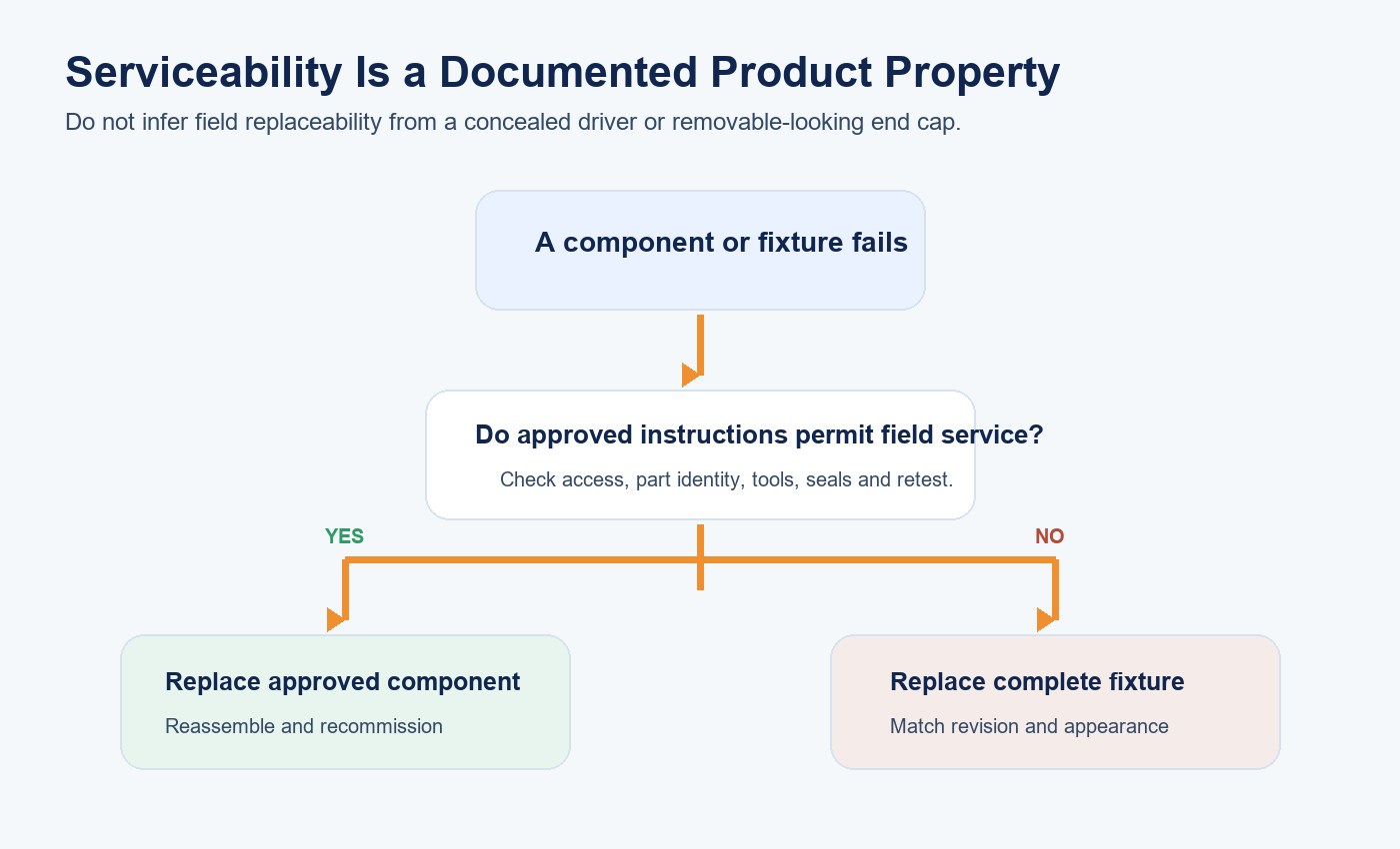
If the complete fixture is the service unit, plan spare quantities, storage and future visual compatibility. A physically fitting replacement can still differ in CCT, output, diffuser appearance, connector revision or control behavior. Record the approved revision and define how substitutions will be reviewed.
For broader retrofit choices, use the fluorescent-lighting replacement solution to compare complete fixtures with lamp-based routes.
Approve a Representative Sample and Linked Row
Approve the complete product: housing, diffuser, LED board, driver, connectors, switch, clips, cable and markings. Verify dimensions, input power, light output, color, distribution, flicker behavior, temperature and installation fit against the documents.
Then build a representative linked row, ideally including the proposed maximum or a justified worst case. Record startup behavior, current at the feed, voltage at the final unit, connector temperature, alignment, switching behavior and the result of a controlled fault or interruption where required by the project plan.
Retain a golden sample, approved drawing, BOM or component-control record, wiring diagram and test results. New Lights’ factory and manufacturing capabilities describe the manufacturing context for sample control and production coordination.
Prepare the T8 Integrated Fixture RFQ
Provide length, quantity, power, supply, mounting surface, clip spacing, linked-run arrangement, controls, ambient condition, target light levels and maintenance strategy. Request the exact model and construction, wiring diagram, connector ratings, linked quantity, photometry, temperature evidence, markings, installation instructions and certificate scope.
For a bounded configuration review, contact New Lights with the layout, circuit, selected input and expected number of fixtures per run.
| RFQ item | Supplier response | Approval evidence |
|---|---|---|
| Product identity | Exact model, length, power and construction | Quotation, label, drawing and sample agree |
| Electrical path | Feed end, pinout, conductor and connector ratings | Approved wiring diagram and linked-run calculation |
| Optical result | Output, distribution, color and TLM | Model-level report and representative mockup |
| Installation | Clip spacing, orientation and clearances | Drawing and site coordination accepted |
| Service plan | Approved component service or whole-unit replacement | Instructions, spares and revision strategy recorded |
| Change control | Controlled critical components and notification rule | Production order tied to the approved configuration |
Frequently Asked Questions
Can a T8 integrated LED fixture accept a replacement T8 tube?
Normally no: an integrated fixture is supplied with its own LED board and driver. Confirm the exact drawing because product categories with similar shapes can use different internal architectures.
How many T8 integrated fixtures can be linked?
Use the model-specific limit for the selected voltage, power, connector and ambient condition. Check steady current, inrush, voltage drop, protective devices and the connector path; do not derive the final limit from watts alone.
Does an integrated fixture have a replaceable driver?
Only when the approved service instructions and parts information say so. A concealed or removable-looking driver is not enough to establish field replaceability.
Is an integrated T8 fixture always more efficient than a replaceable tube system?
No. Compare complete-system input power, delivered light, distribution and application results. Product architecture alone is not an efficacy result.
What should be tested in a linked sample row?
Verify current, startup, end-of-run voltage, connector temperature, alignment, switching and control behavior, light consistency and any project-specific fault response.
Editorial Sources
- New Lights, “Surface-Mounted T8 Integrated LED Fixture”: https://www.new-lights.com/products/led-linear-fixtures/linear-battens/t8-integrated-led-fixture/
- U.S. Department of Energy, “LED Basics”: https://www.energy.gov/cmei/ssl/led-basics
- U.S. Department of Energy, “Lighting Specification Guidance for Schools”: https://integratedlightingcampaign.energy.gov/sites/default/files/2025-01/lighting-spec-guidance-school_nov24.pdf